
First of all if you don’t know what the hell is SunVox then here is official information from the source:
SunVox is a small, fast and powerful modular synthesizer with pattern-based sequencer (tracker). It is a tool for those people who like to compose music wherever they are, whenever they wish. On any device. On any system. And it’s free for most of the systems, except the Android and iOS.
https://warmplace.ru/soft/sunvox/
Now you know what SunVox software is. I want this to be standalone SunVox Raspberry Pi synth and be portable and independent from the computer as much as possible, let just say DAWless style or rather portable DAW?
There is a lot of examples on YouTube how to run SunVox headless on Raspberry PI Zero. I want this to be full fledge SunVox standalone synth with all possible features. To do that we need a case to be able to fit LCD screen, Raspberry PI and all peripherals like sound card and MIDI interface.
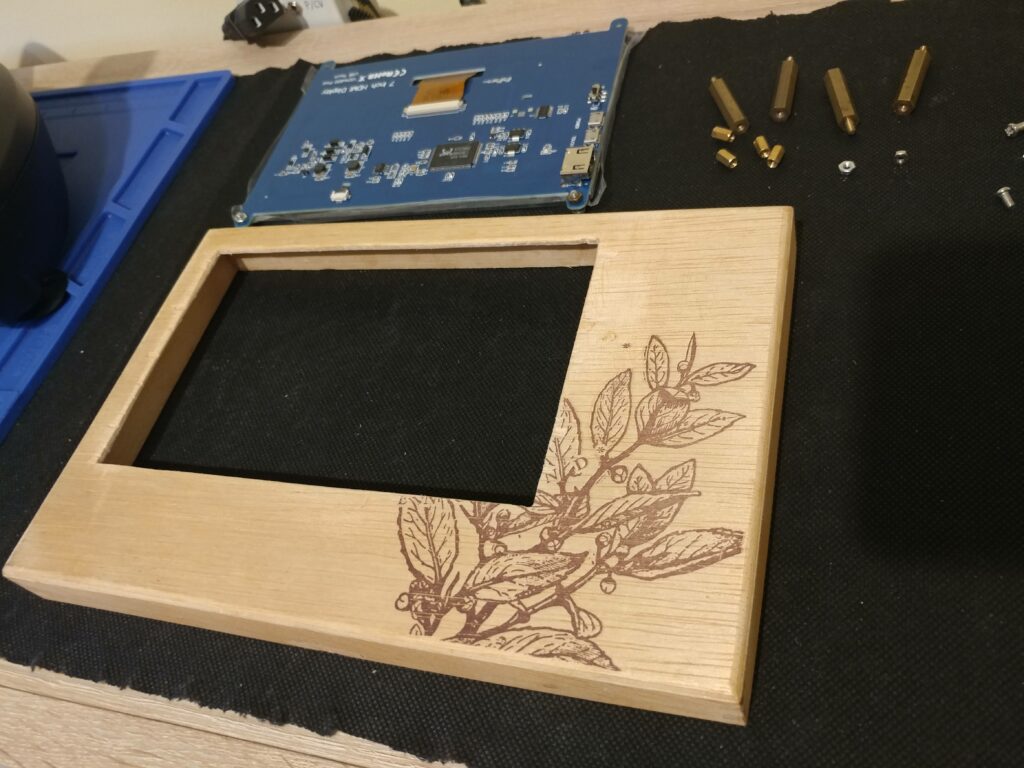
Here is my choice, a Tetley wooden tea box! Why? Simple, it’s a garbage! Yes I had this empty box that I was about to throw away but I noticed that the wood is easy to work with, that means it has high wood density, not too soft not too hard, so you can cut various shapes in it like in metal.
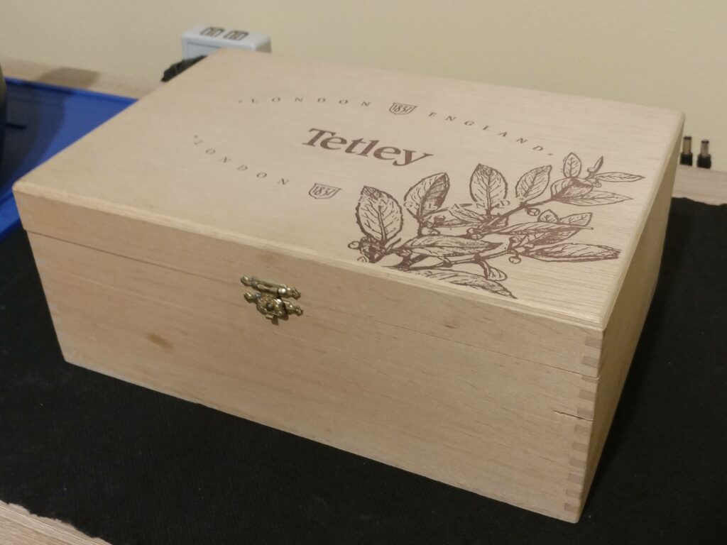
Box dimensions are almost perfect to fit LCD screen, only we need to cut on height.
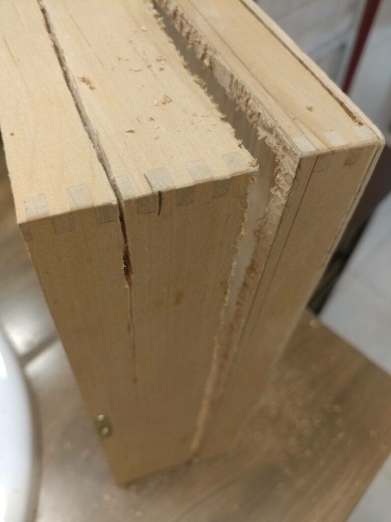
I cut about 2 cm from the bottom to match the original openable lead from the box, I have removed the metal hinges and clasp.
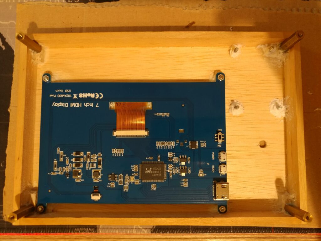
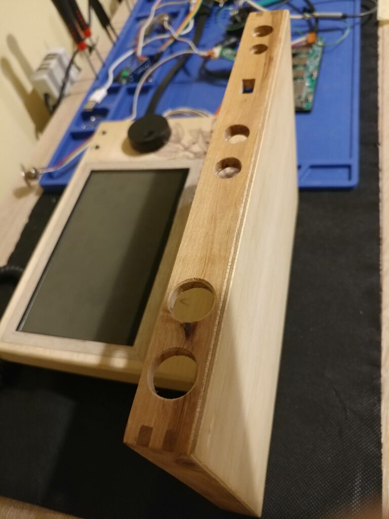
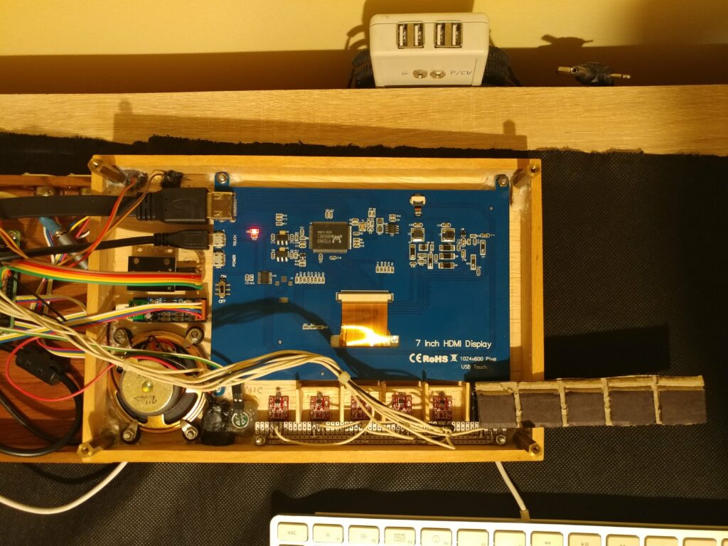
Next we need to cut a hole for the screen on the top lead. I’m using 7″ touch sensitive HDMI LCD panel. I want to have much work space as possible in the SunVox GUI.
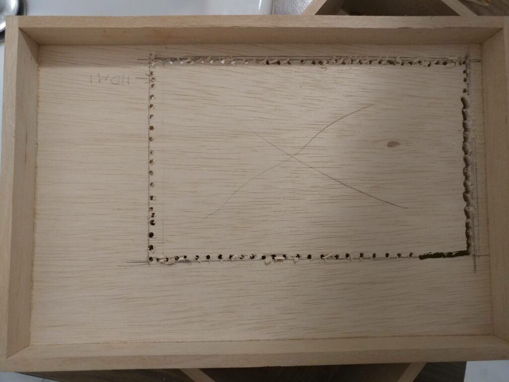
I used drill to make a lot of small holes and then it was easier to cut rest with the saw. I used the same technique for the bottom cover.
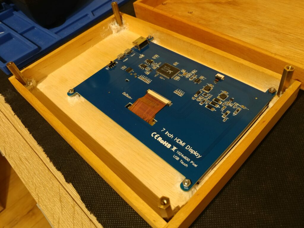
Next we need to attach LCD screen to the cover. Fortunately LCD has a mounting brackets that we can use.
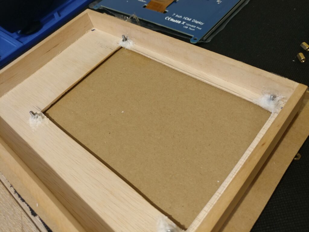
The only thing we need to do is to use some universal (wood/metal/glass) glue to attach some M2 screws for each mounting bracket.
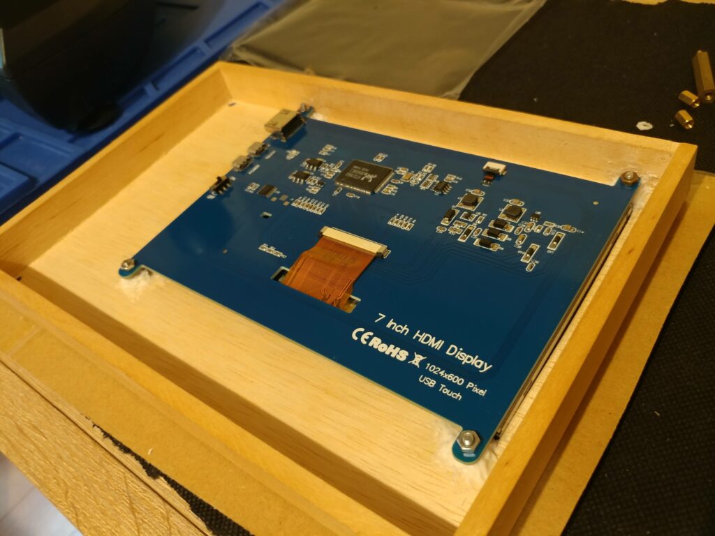
This will be visible only inside, no holes need to be drilled so nothing will be visible outside.
The same technique can be used to attach top and bottom cover together. But this time we will be using some brass hex M2 standoffs.
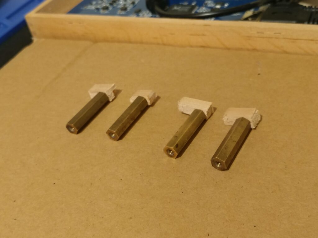
Again use wood metal glue and attach brass standoffs on each corner to the top cover.
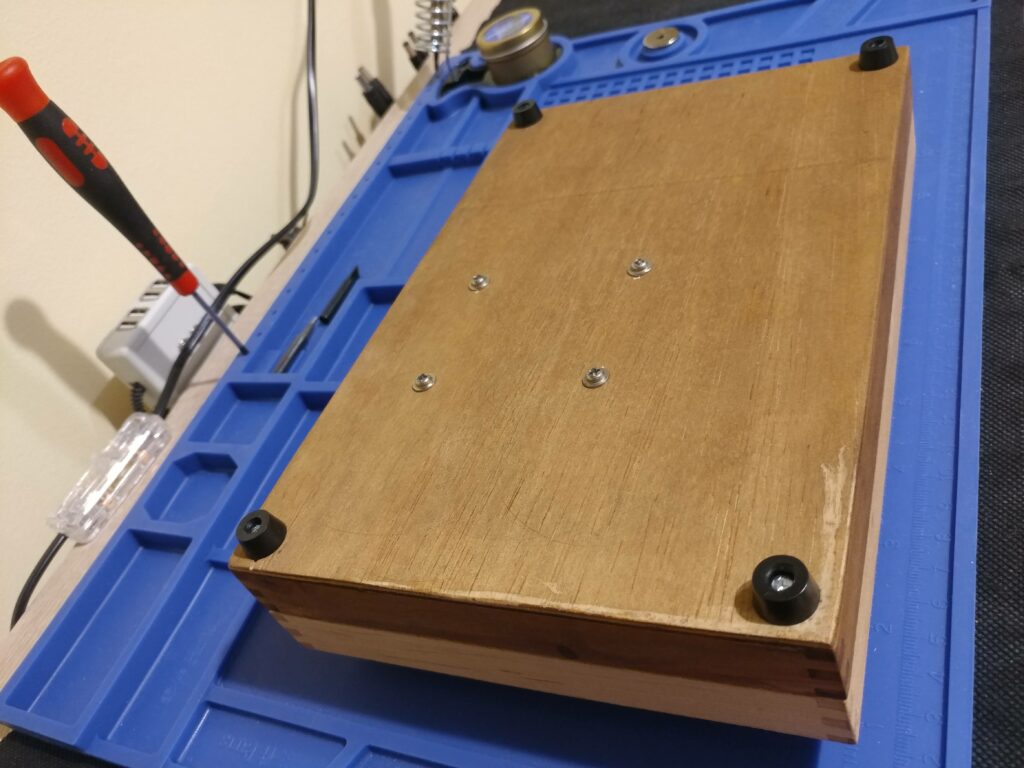
This time we will have to drill 4 holes on the bottom cover to use M2 screws to attach both covers.
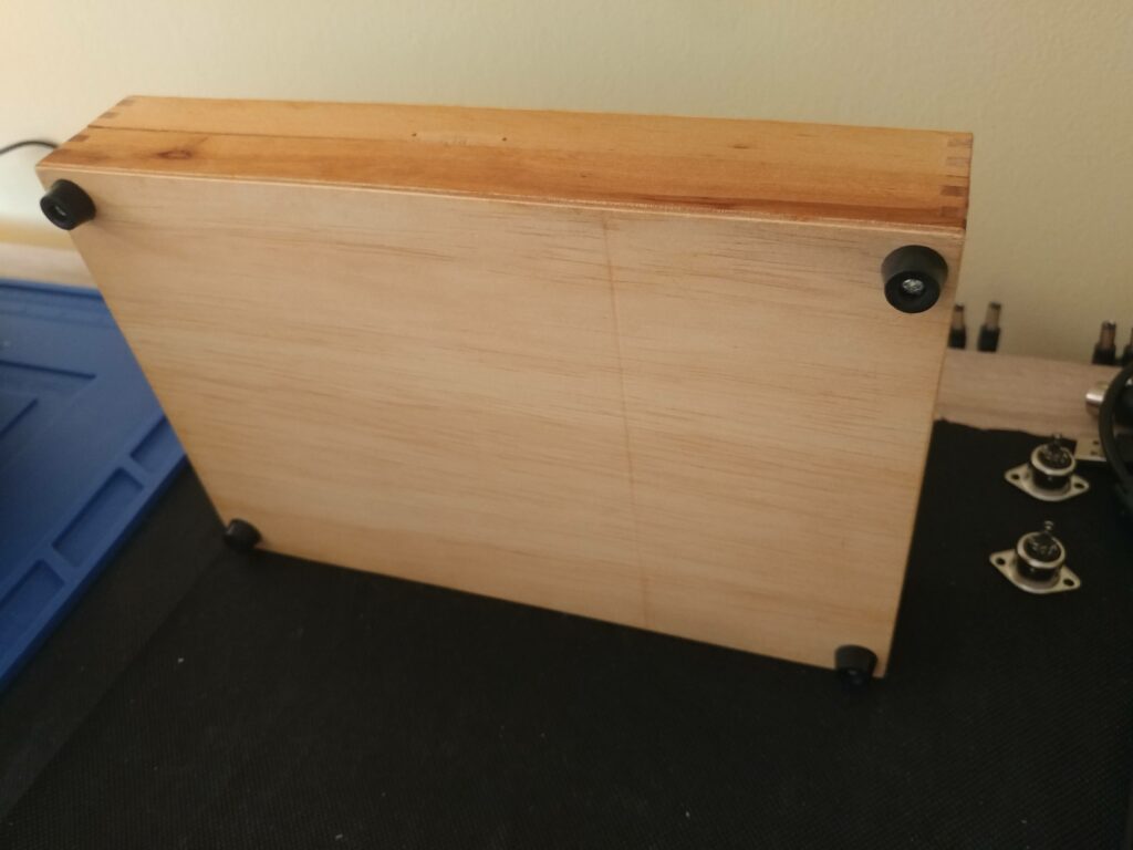
We can hide the holes with some rubber feets so we will have strong and neat connection.
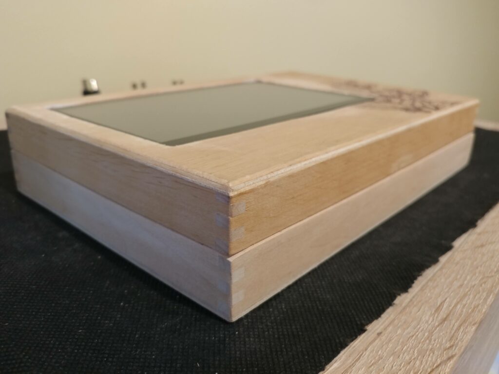
We can use wood fill to cover some cracks and cavities, then use some sanding paper to remove scratches and even out all sides of the cover and make it nice to touch.
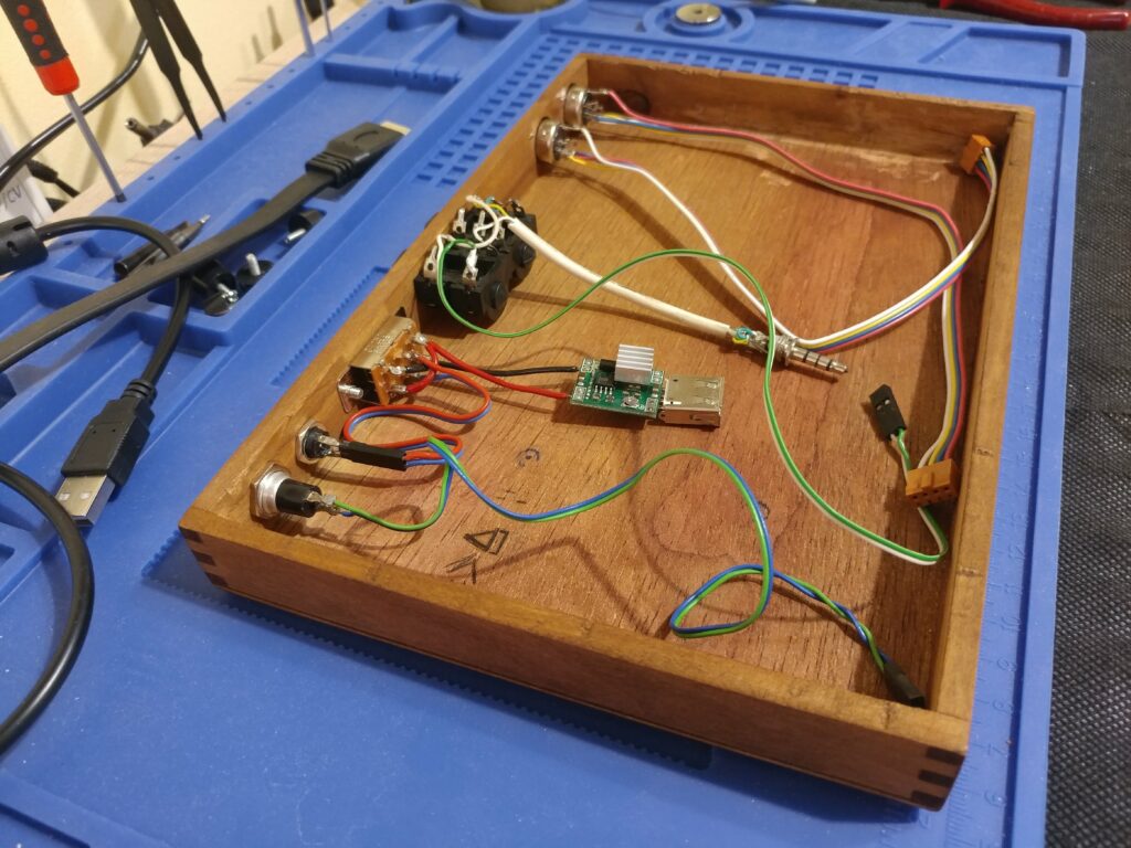
Now we need to test connect everything together and make sure everything works as it should.
I’m using left over parts and reuse some old ones that I don’t need. For the brains of the synth I will use Raspberry Pi 3 Model A+ because it has enough power to run SunVox and it’s cheap 😀
Of course I recommend to use Raspberry Pi 4 since it has much more memory. But SunVox will run on all Raspberries, it’s not demanding software 🙂
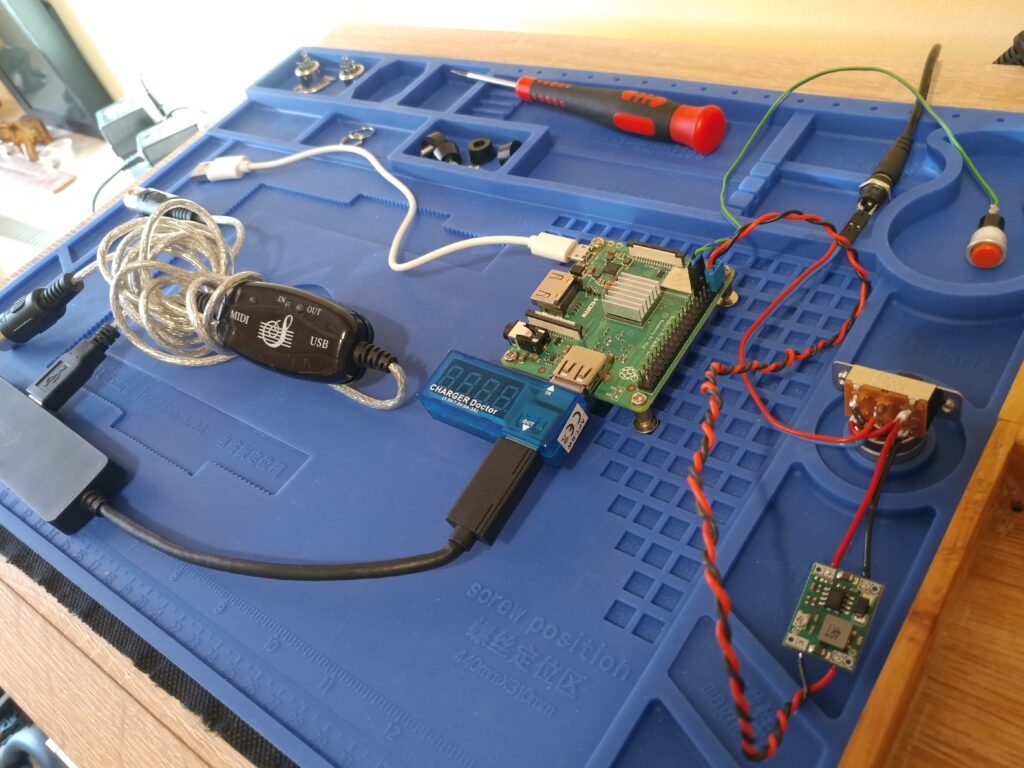
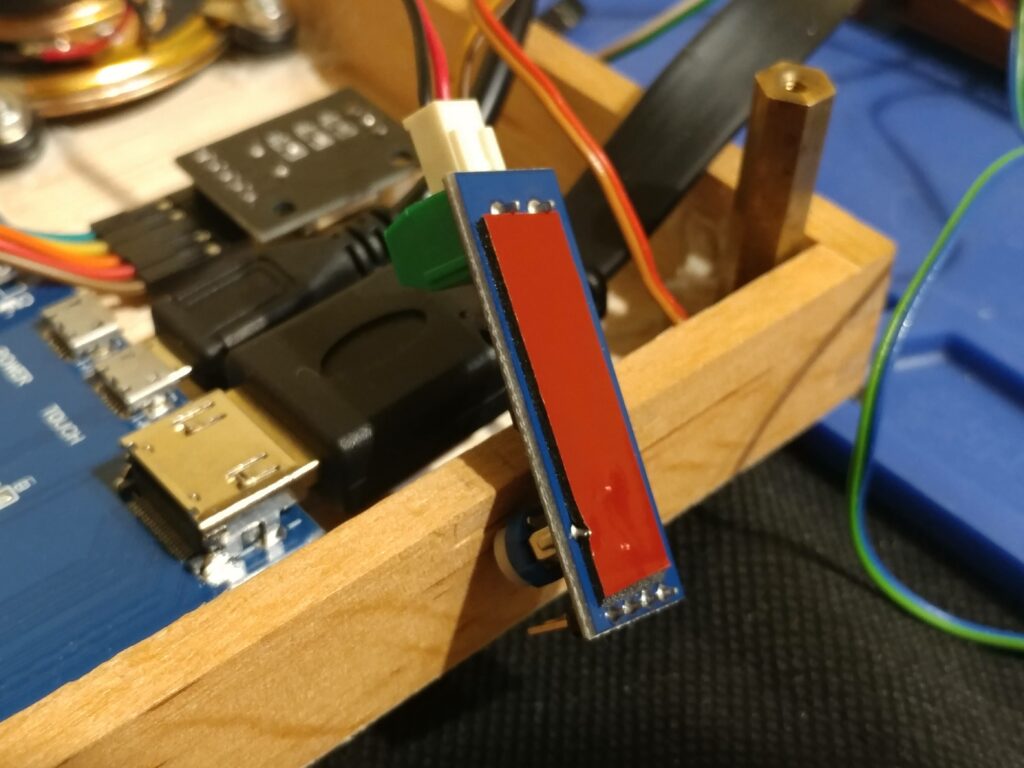
For the heart of the synth I will use HiFi usb sound card. Since Raspberry Pi 3 A+ has only one usb port and we need to attach more usb devices like simple cheap MIDI interface and LCD touch function. We must use some usb hub.
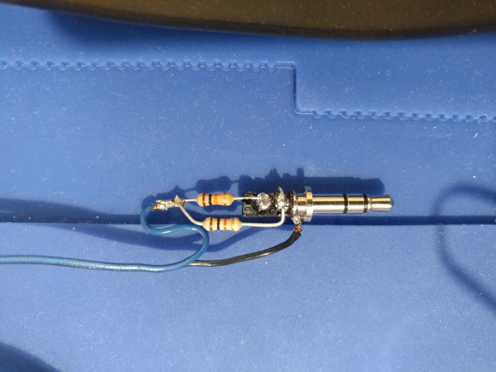
USB sound card has trrs 3.5mm socket on the out so we need to break this connection with one 3.5 trrs jack to two 6.3 mono and stereo sockets. Mono socket is for line IN, yes SunVox can sample! Stereo socket is our line OUT.
Here is the schematic of the connection to USB sound card:

Our test setup is working! As you can see I have stripped USB hub and MIDI interface from it’s plastic covers, since everything will be packed up in the box we will make more room and we can release some build up heat that way.
Also important note about the power supply here is that Raspberry Pi 3 takes about 2.5A peak and 1.5A 5V steady voltage. I used small 3A DC to DC step down power converter module that you can use to make 5V out of 9V up to 16V, also I have used reverse polarity switch so I can use any power supply or wall wart capable to produce above 2A steady voltage.
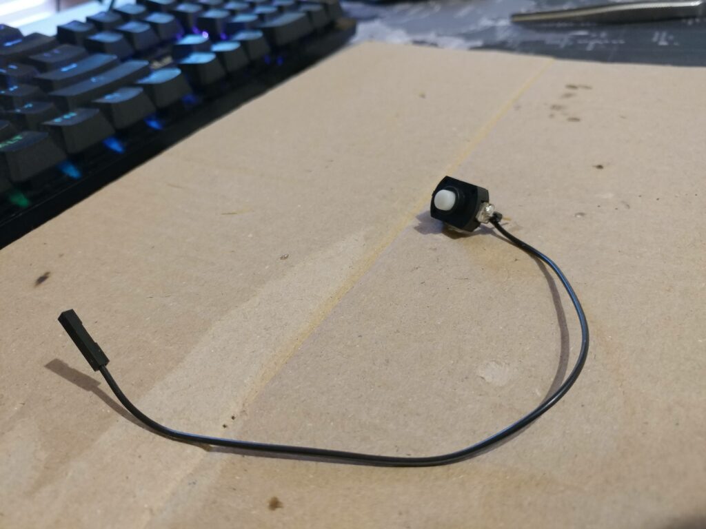
In the test rig I connected some momentary switches to a Raspberry Pi GPIO port to test out some functionalities like software power on/off. Later we will replace switches for touch sensors but we need one button to handle proper linux power off and on without corrupting our SD card. To do that we only need to connect one switch to GPIO3 (pin 5) and any GND pin (I used pin 6).
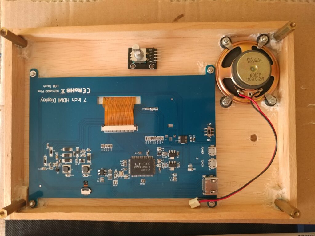
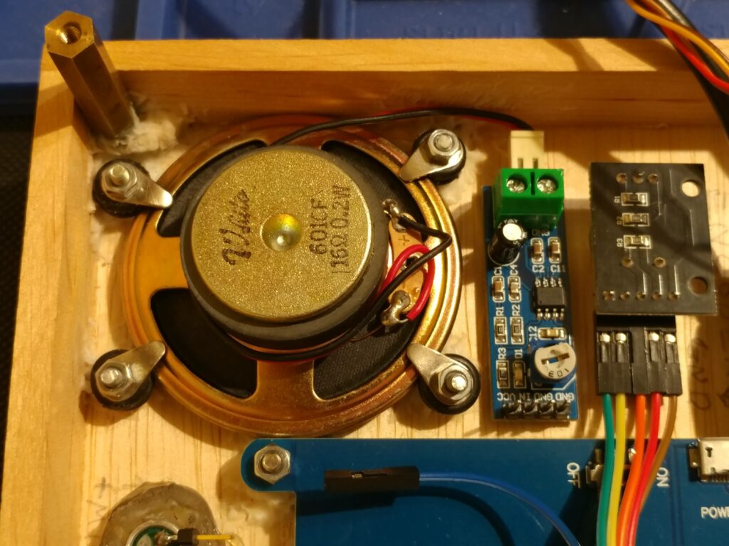
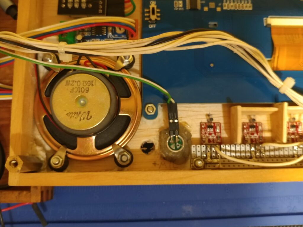
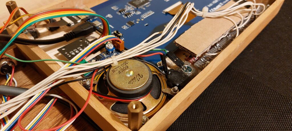
Next we need to attach internal speaker and drill a hole for our rotary encoder in the top cover. We are using the same technique as for LCD again, gluing four M2 small screws and secure speaker with some gills and nuts. Also I used some rubber washers to remove vibration from the speaker.
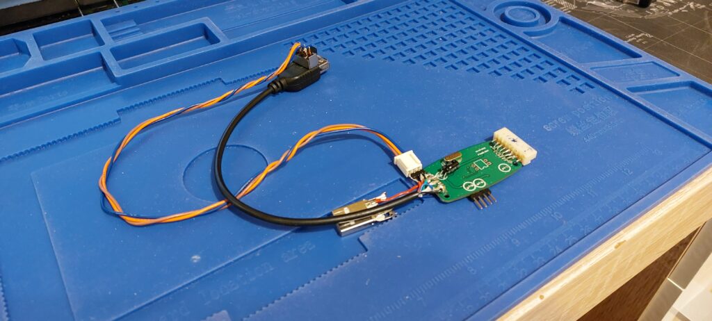
As for our encoder I recommend to use encoder module, since it has already some pullup resistors that will help with the signal, it will be easier to use it with Python script on the Raspberry Pi.
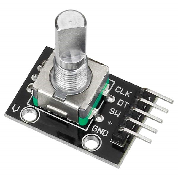
Encoder is connected as follow: CLK > PIN37 (GPIO26), DT > PIN38 (GPIO20), SW > PIN40 (GPIO21), GND > PIN39 (Ground), + > PIN1 (3V3)
I had to shorten the shaft of the encoder since I will use large but flat knob wheel.
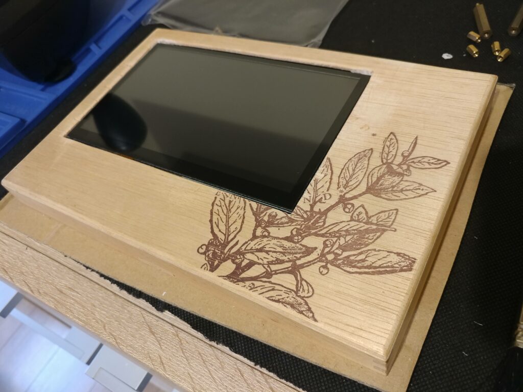
Also I added some furniture finishing adhesive tape around the LCD screen to hide the top cover uneven cut. Also called “hiding the crimes” 😉
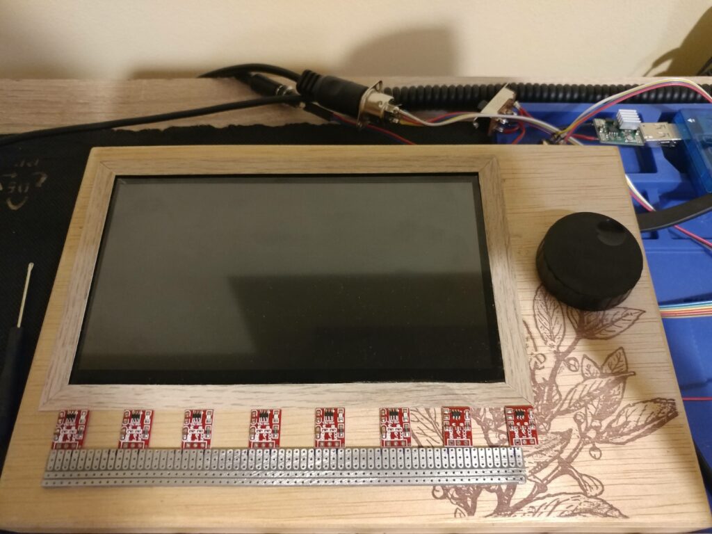
Nex part is to add our touch sensors instead of momentary switches. This will be our SunVox shortcut keys, play, stop, record and other functionalities since we had only touch screen to control the synth, this will be much easier and faster.
Now interesting fact about this type of touch sensors (TTP223) is that when you power up the sensor it will calibrate itself to the surface above touch field. That means it will work under different density materials including wood!
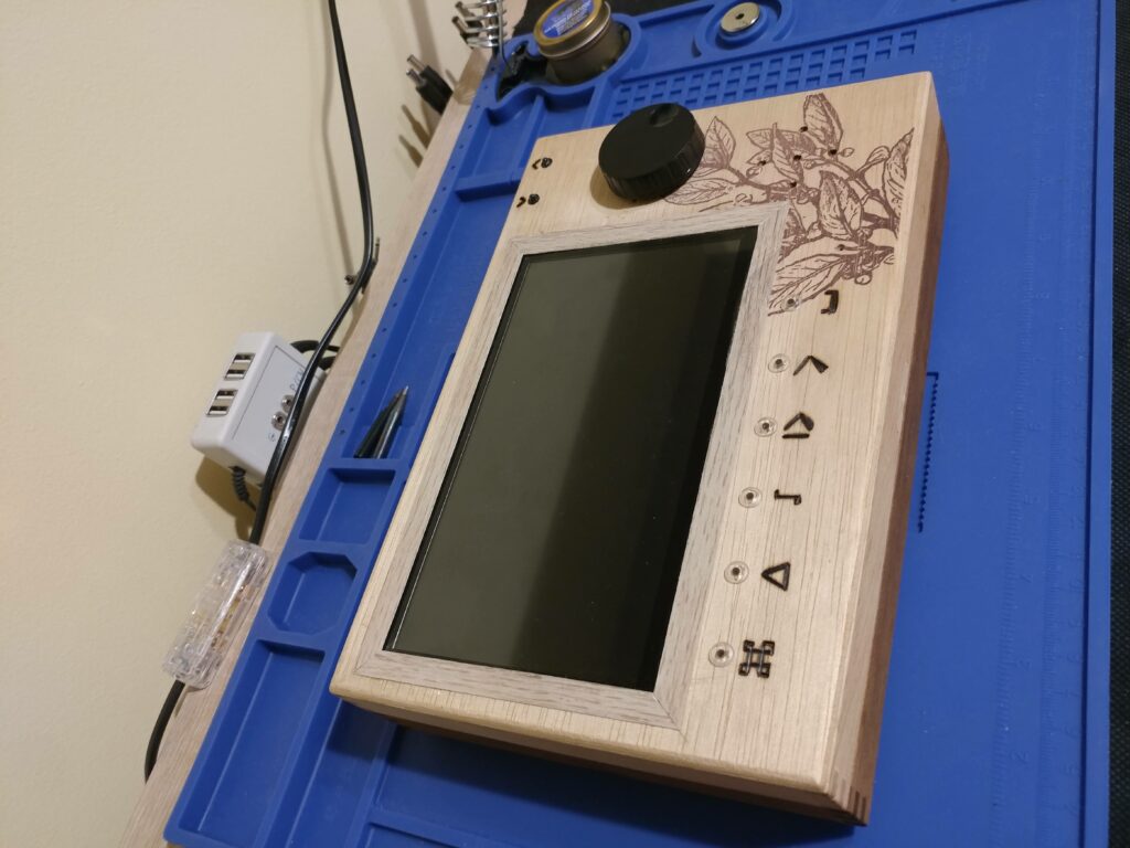
Since sensor led is lit upon touch detection I had to drill holes in the cover and use some clear plastic studs to bring the light to the front, to be able to see which sensor Im touching. There is a problem with that because sensor leds are too bright and light bleed is visible on adjacent studs. You will need to stop it by covering leds on both sides with something. I have used some ice sticks that I cut and glued to the cover. That will do the trick!
I used clear plastic studs that are plexiglass joining pins, but I guess you can leave empty hole or use some clear glue to cover the hole.
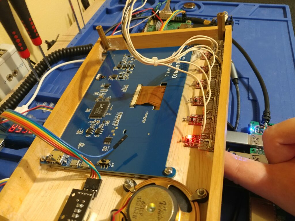
I have soldered all six sensors to a common VCC and GND rail on some perfboard and made some wire harness scavenged from old audio equipment. Each wire from touch sensor I/O port must be connected to the separate GPIO port. Common VCC to any free 3V3 pin as same for GND.
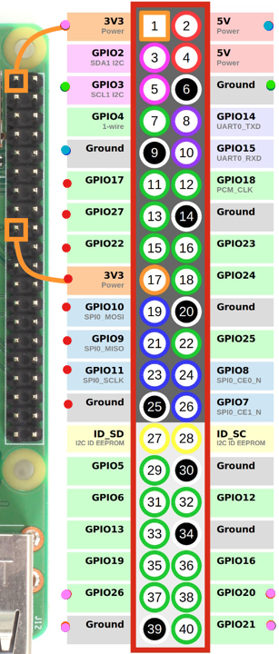
My scavenged harness had standard raster socket for 8 pins, luckily enough it fits Raspberry PI GPIO header from PIN25 (Ground) up to PIN11 (GPIO17) with PIN17 (3V3) in the middle! (red dots on header diagram picture above)
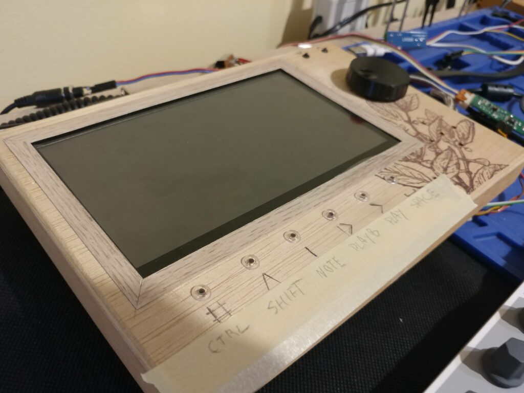
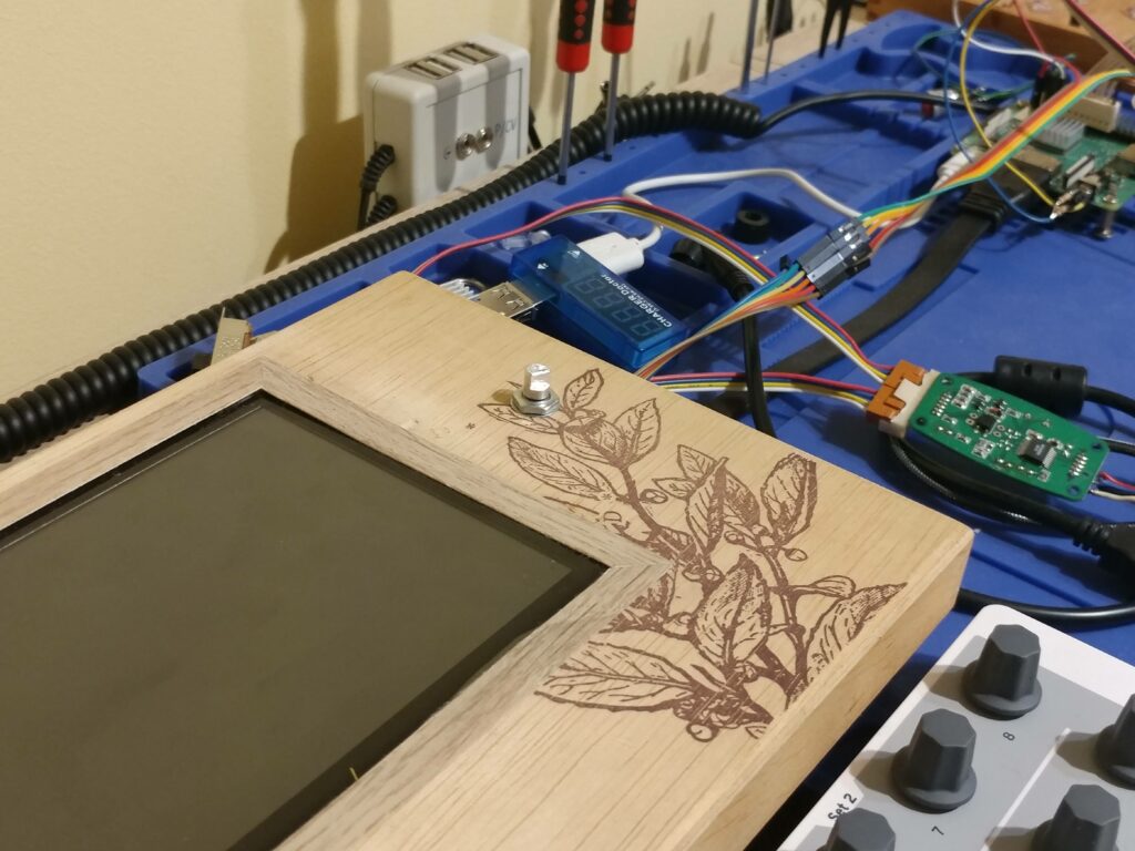
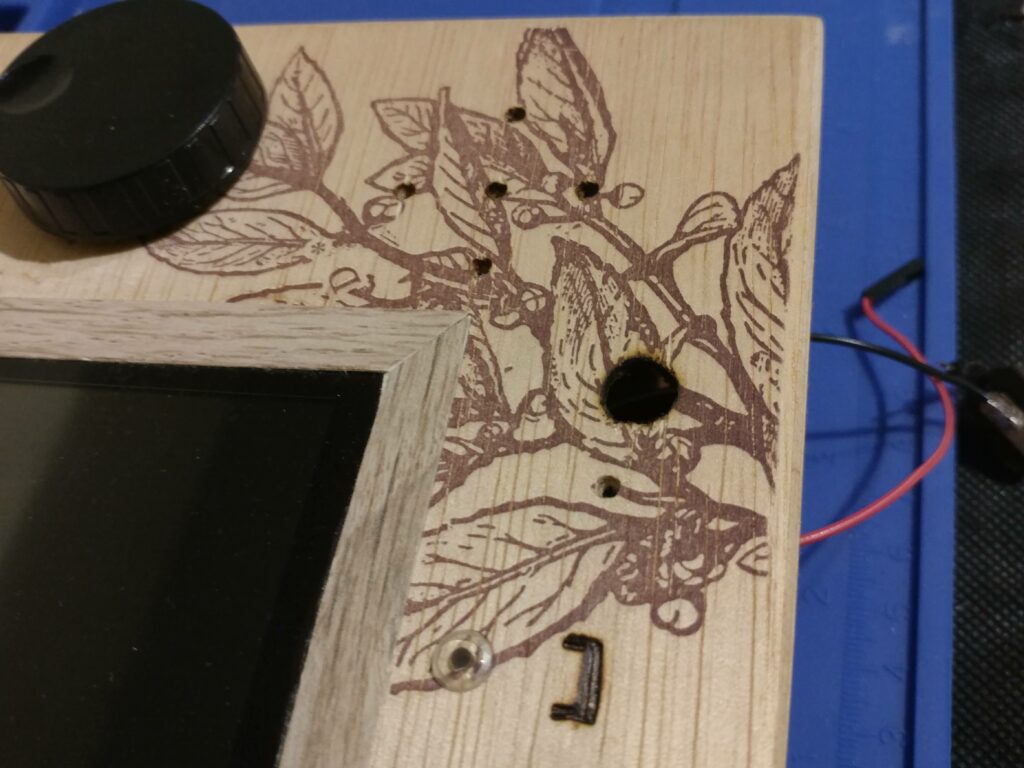
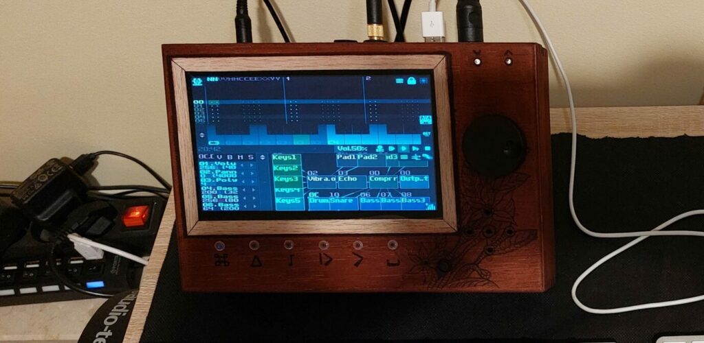
Now I had to make decision what functions I want to have available from touch sensors and design appropriate markings. I decided and made wood burns with the soldering iron knife tip.
From the left we have: Ctrl, Shift, Dot (in SunVox acts as D4 note, but with Shift it switch to next module), F10 (play from beginning), F9 (play/stop), F12 (stop all) keys, that we will have to emulate pressing by touching sensor with our clever Python script running in the background 😉
Also I made couple small holes for speaker to hear it better and two holes above encoder knob in the top cover for MIDI IN and MIDI OUT leds, secure them with some hot glue.
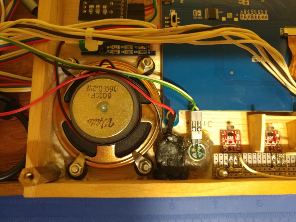
For my setup I wanted to have internal speaker that I can select from SunVox instead of USB soundcard. To make this work we will need to use Raspberry Pi internal sound card 3.5mm jack output. But it’s not enough to drive the speaker so we will need to use small sound amplifier module.
Amplifier needs +5V and GND connection from the GPIO ports (blue dots on the header diagram) and it needs mono signal so we need to sum audio from both channels from the Raspberry Pi headphone out, to one channel using some resistor. I used 1k on both channels.
Connect speaker to the amplifier out header and secure amplifier with double sided tape to the top cover.
One flaw of this solution is that when we want to use WiFi on Raspberry Pi for example download some files or make edits in configuration. Our sound amplifier will produce some weird noises on the speaker due to WiFi signal disturbance.
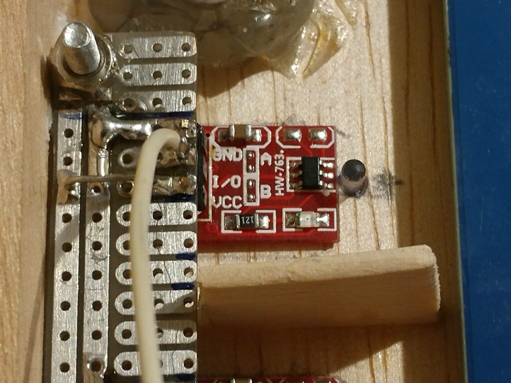
Best solution is to turn off amplifier when using WiFi, you can do that with any on/off switch on 5V or GND line. I placed my switch on the front cover but I need to make a big hole. Also I decided to add internal microphone so need to make another small hole next to switch as well.
As you can see I made pin connectors on the switch and mic because mic is soldered to our line IN 6.3 jack connector which will sit on the bottom cover as well as Raspberry Pi. Switch and the mic is on the top cover, so it must be detachable. Microphone is active when there is no jack in the line IN socket.
I found suitable space next to the touch sensors, mic and switch is secured with some hot glue.
Now we need to take care of our bottom cover. We need to make some fancy holes for our connectors 🙂
Also this is good time to test out some wood stain on the inside of the covers and see how it looks like.
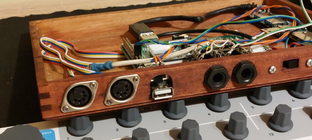
From the left we have our momentary switch for soft power On/Off, next we have our power socket, polarity switch (this square hole can be done with some fine wood file), next is audio line IN and OUT 6.3 jack sockets, last we have MIDI IN and OUT 5 din sockets.
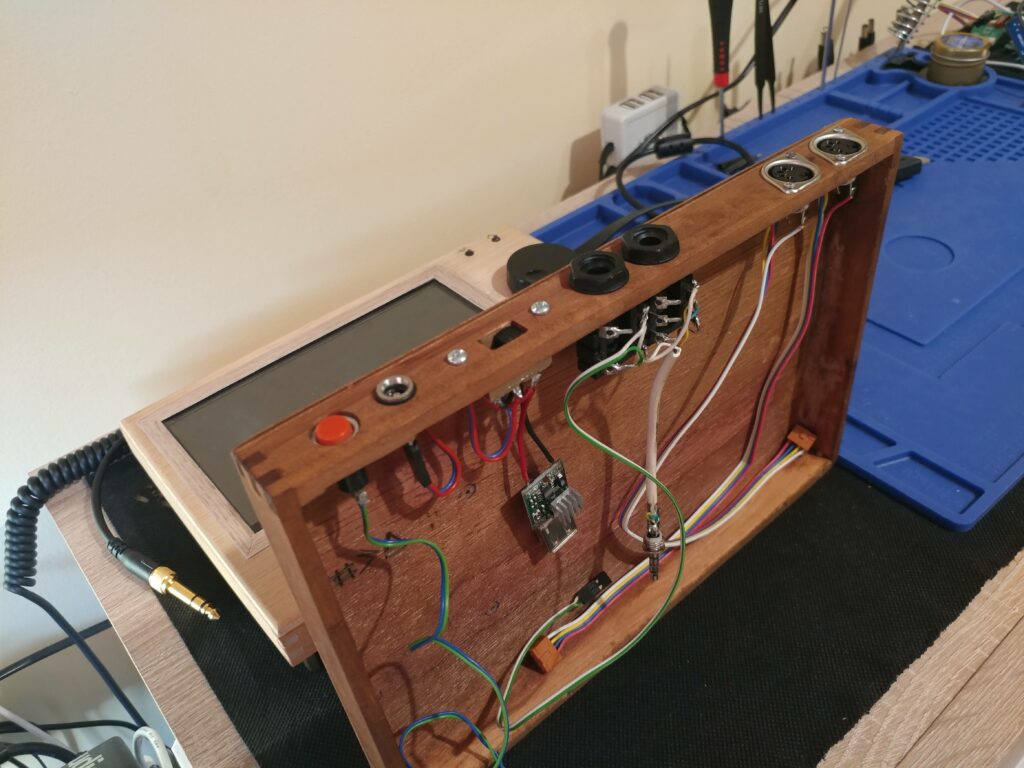
As you can see all wires have pin headers so they can be detached easily. Also I tested different wood stain colors on the bottom cover. This is hard decision 🙂
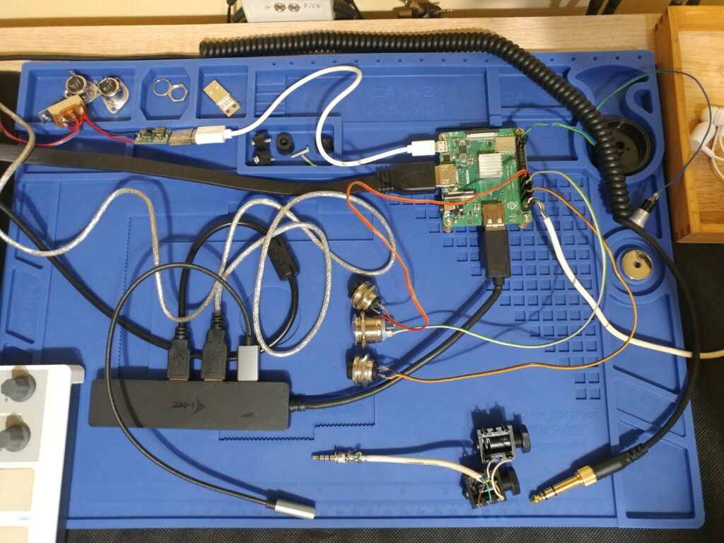
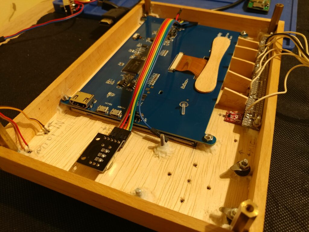
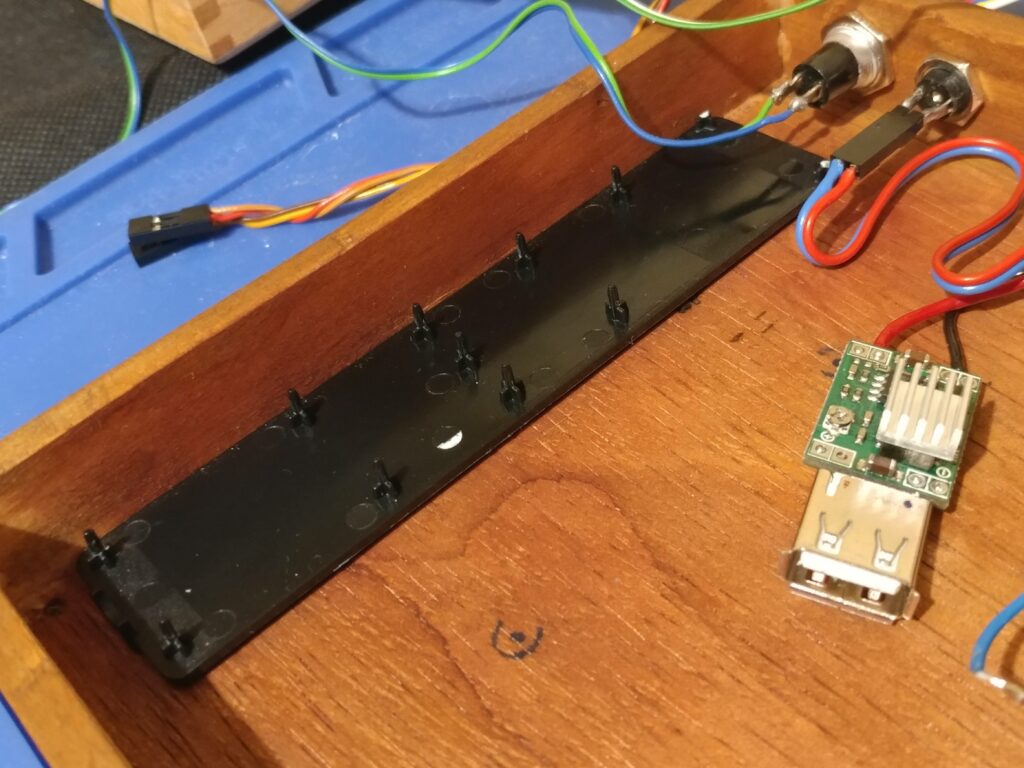
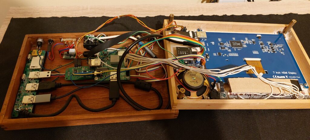
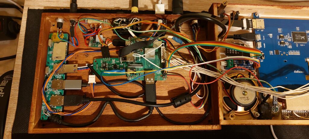
Now another hard part is to place everything inside the bottom cover, I started from placing USB hub, I just strip down the plastic cover and glued with double sided tape the bottom half to the wooden cover.
Raspberry Pi is attached on the middle of the cover with some screws to make strong connection since everything is connected to it.
Now we need to test fit every component and check if the top cover will close.
There was still problem with light bleed from the sensors leds, so I come up with simple idea to cover them more with some cardboard painted with black marker to kill some more light.
You can glue the cardboard to the wooden ice sticks.
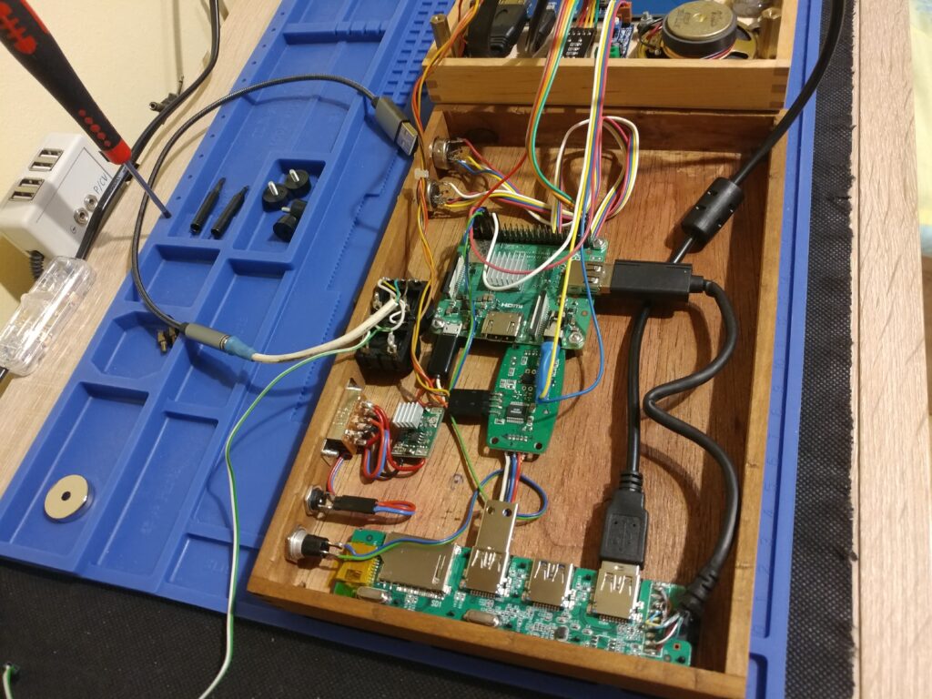
This is how our test connections looks like 🙂
To make more room inside the cover you can use some zip ties to hold some wires together. Also I replaced chunky and stiff HDMI cable that came with the LCD, with smalle, thin and flexible HDMI ribbon cable.
Then there was enough room to fit one more socket between Line In/Out and Midi In/Out sockets in our bottom cover.
Since my USB hub has only three sockets and all are used up by LCD touch controller, Midi interface and external sound card. I needed to connect some more external devices like keyboard, mouse, pendrive etc.
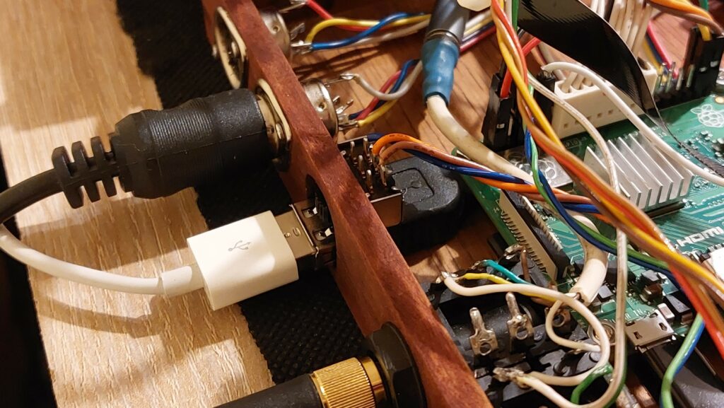
I came up with the idea that I can turn off Midi interface by cutting +5V power line from the hub and redirect it to external usb socket with a switch. Since Midi interface has already custom usb socket soldered to the data lines I can easily solder another socket to it and share data lines. And while I’m using external keyboard, Midi interface is not used anyway so it can be turned off.
Another semi rounded hole on the bottom cover needs to be made since there is a switch on top of the socket I decided to fit all in one hole. My external usb socket is made out of some old usb extension cord so I had to glue it to the cover, it’s not nice solution but you can use dedicated usb panel mounted options.
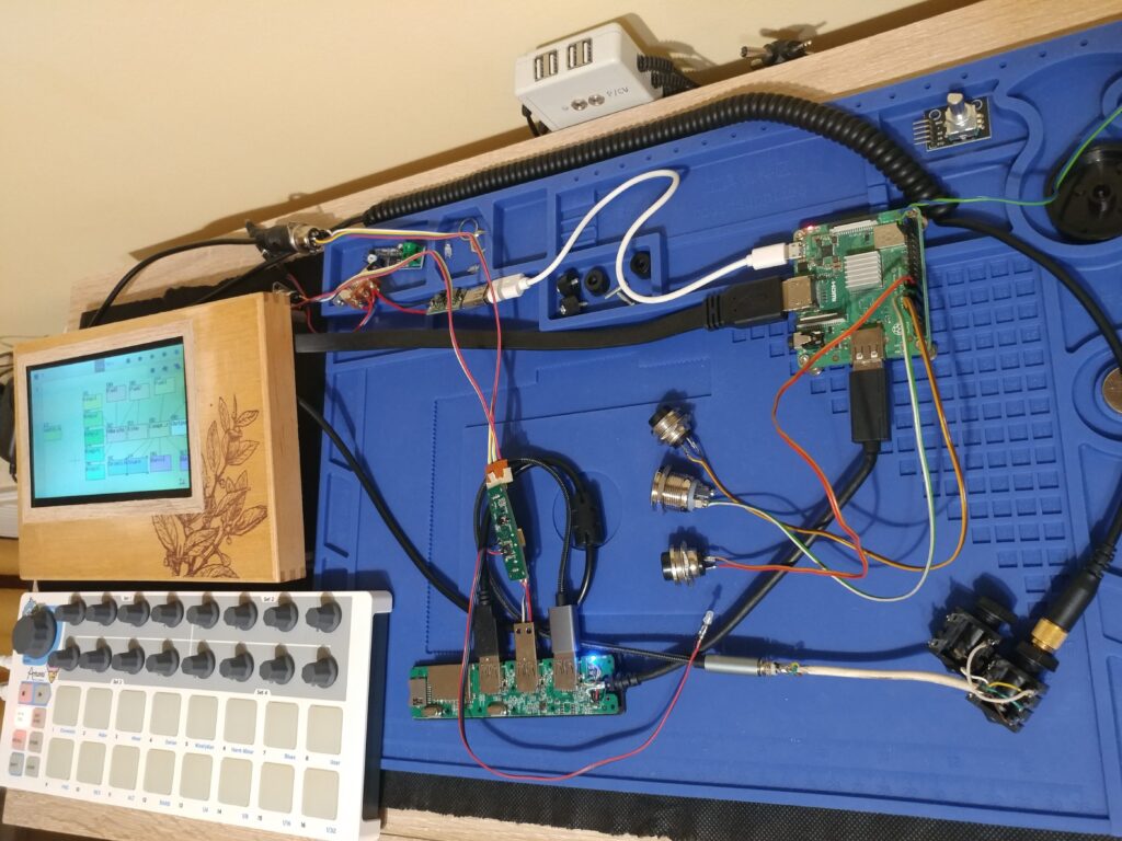
It does not look too bad! Here it is completed internal layout. Don’t forget to screw both halves together!
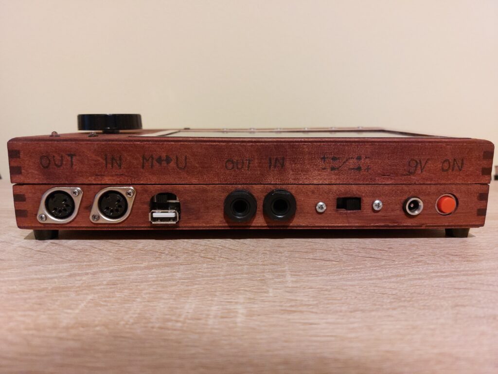
I settled on one wood stain color on both covers. Painted couple of layers and did some markings on the back sockets.
Now we need to install Raspberry PI OS Lite Legacy (Debian Buster) version without GUI. SunVox running on startup as well as encoder and touch sensor controller script in the background. I have pretty decent latency, but you can try installing different Raspberry Pi compatible OS like Manjaro or other Real Time OS. You can find all install instructions in the attachment in the readme.txt file at the bottom of the page.
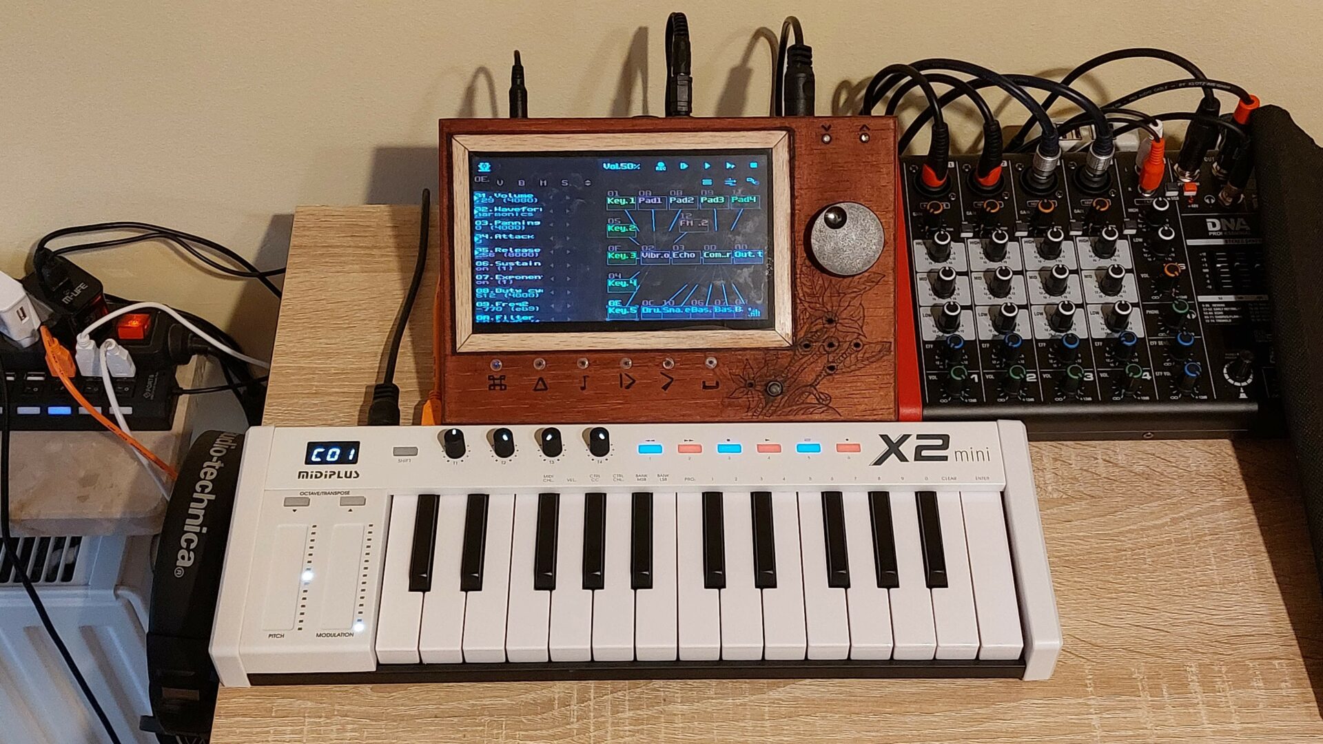
Here is the finished synth. Enjoy! 🙂
Here are the list of most important parts:
- Raspberry Pi 3 A+
- Touch Sensitive LCD screen
- USB hub
- HDMI ribbon cable
- USB 24bit sound card
- USB Midi interface
- TTP223 touch sensors
- DC-DC step-down module
- LM386 audio amplifier module
- Rotary encoder module
For install instructions checkout GitHub project page: