
NTS-1 is awesome little digital programmable synthesizer kit made by Korg.
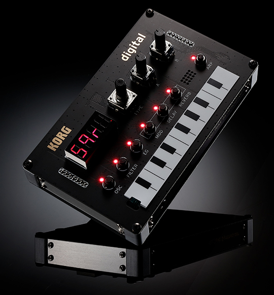
Build it, tweak it, connect it; a world of synthesis at your fingertips!
Korg
It has large potential with added plugins and has powerful digital effect processor. But the self made pcb enclosure design and small SMD audio, sync and Midi connectors are to flimsy and tend to brake a lot.
I wanted to have full size 6.35mm audio jacks and Din-5 Midi sockets to be able to use this synth in my setup, so I need to make my own sturdy case.
I had some wooden box leftovers from my previous project that happens to have perfect size to use for my enclosure!
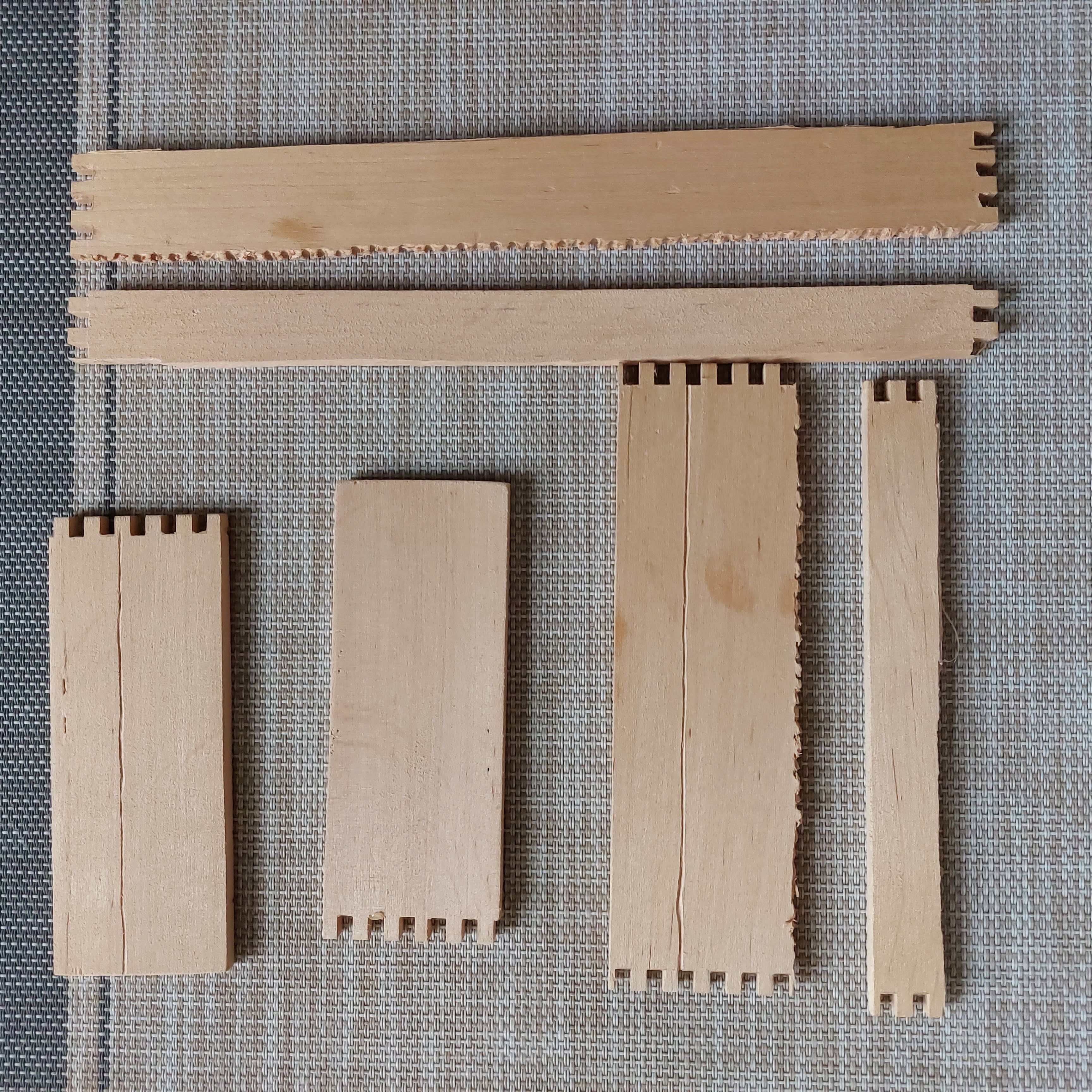
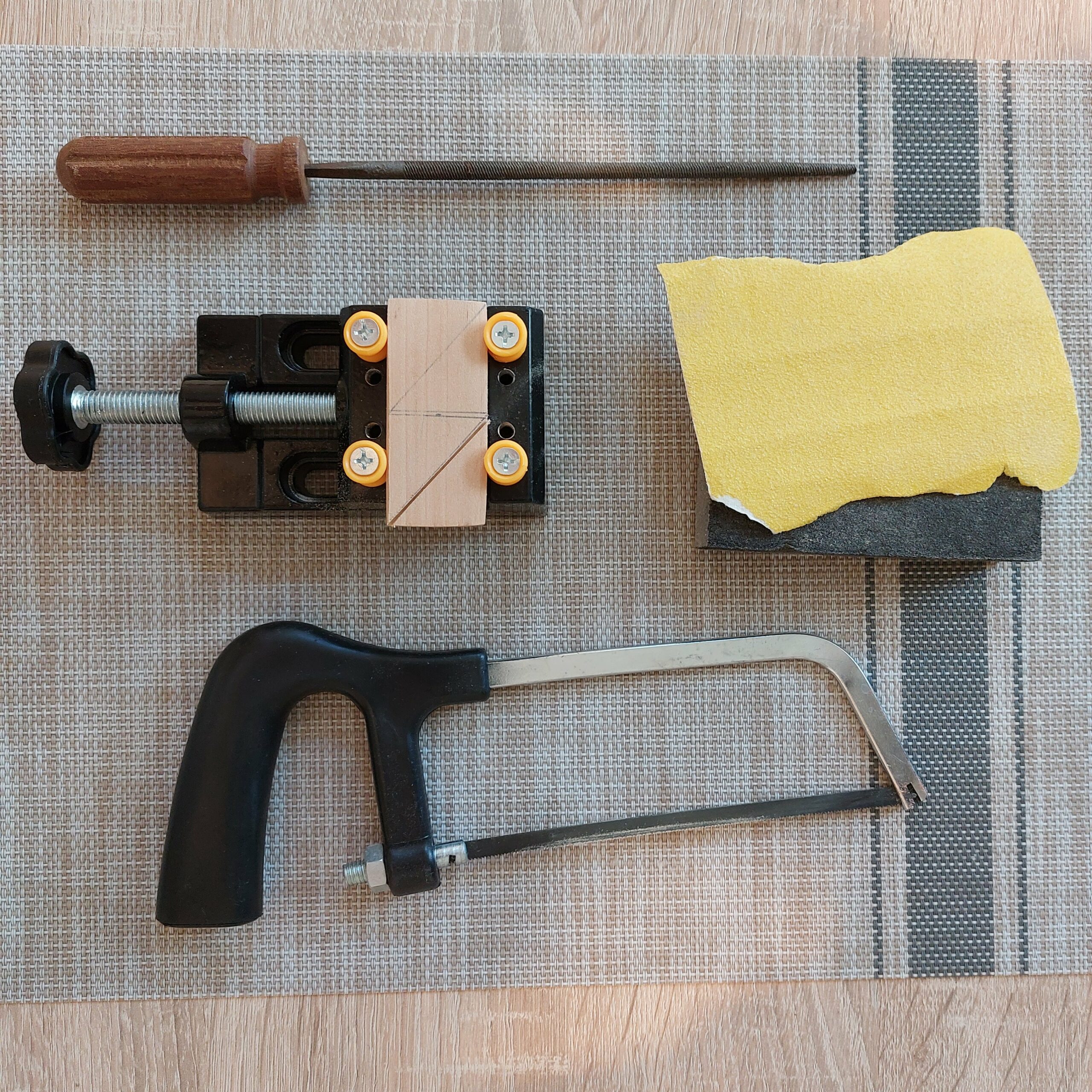
Just need to cut and sand down on the edges with some sandpaper and wood files.
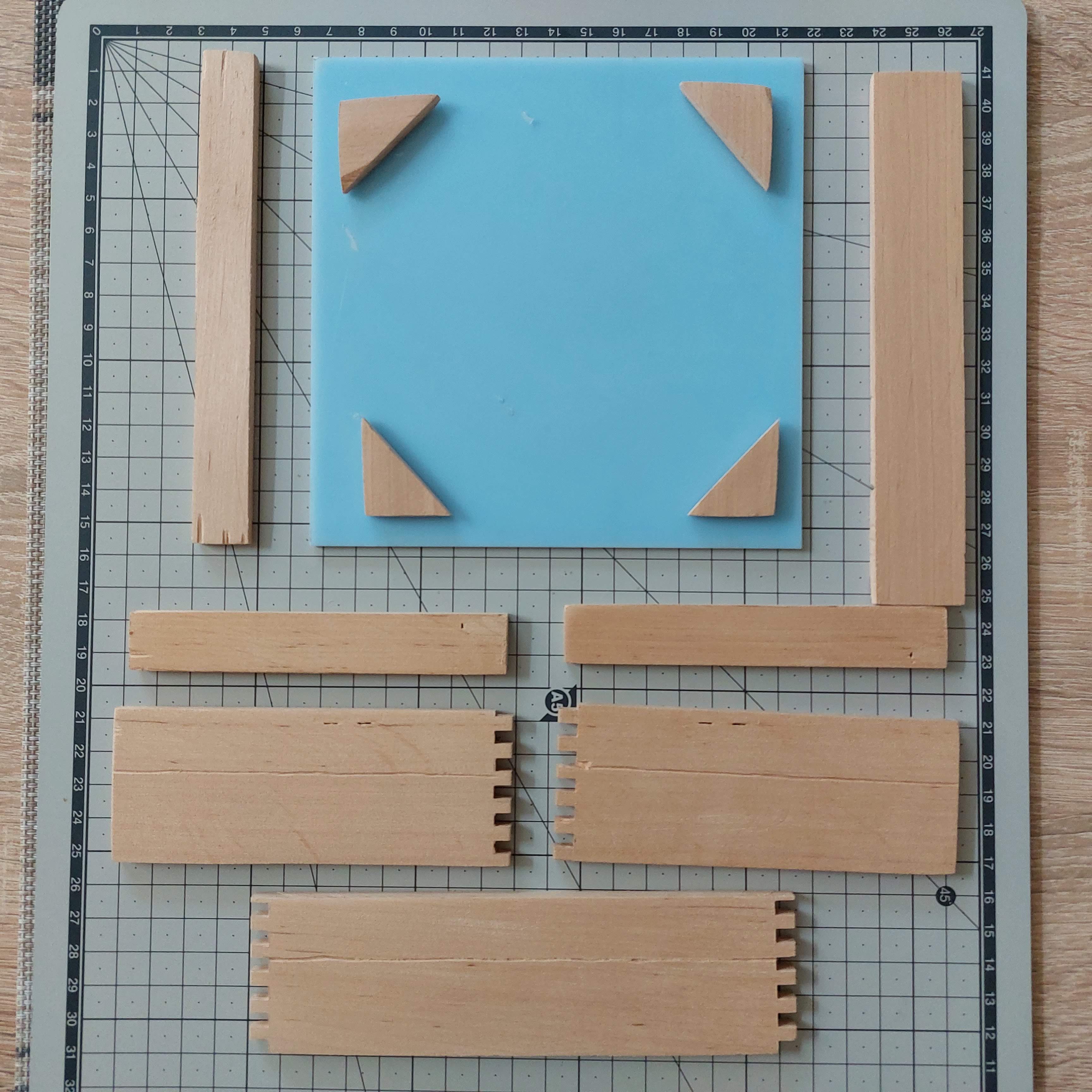
I also found some ABS panel that has perfect dimensions to use as bottom and top cover. I have no idea where I got it from and what is used for but it was trash I guess.
Experimenting with the available pieces for best optimal shape.
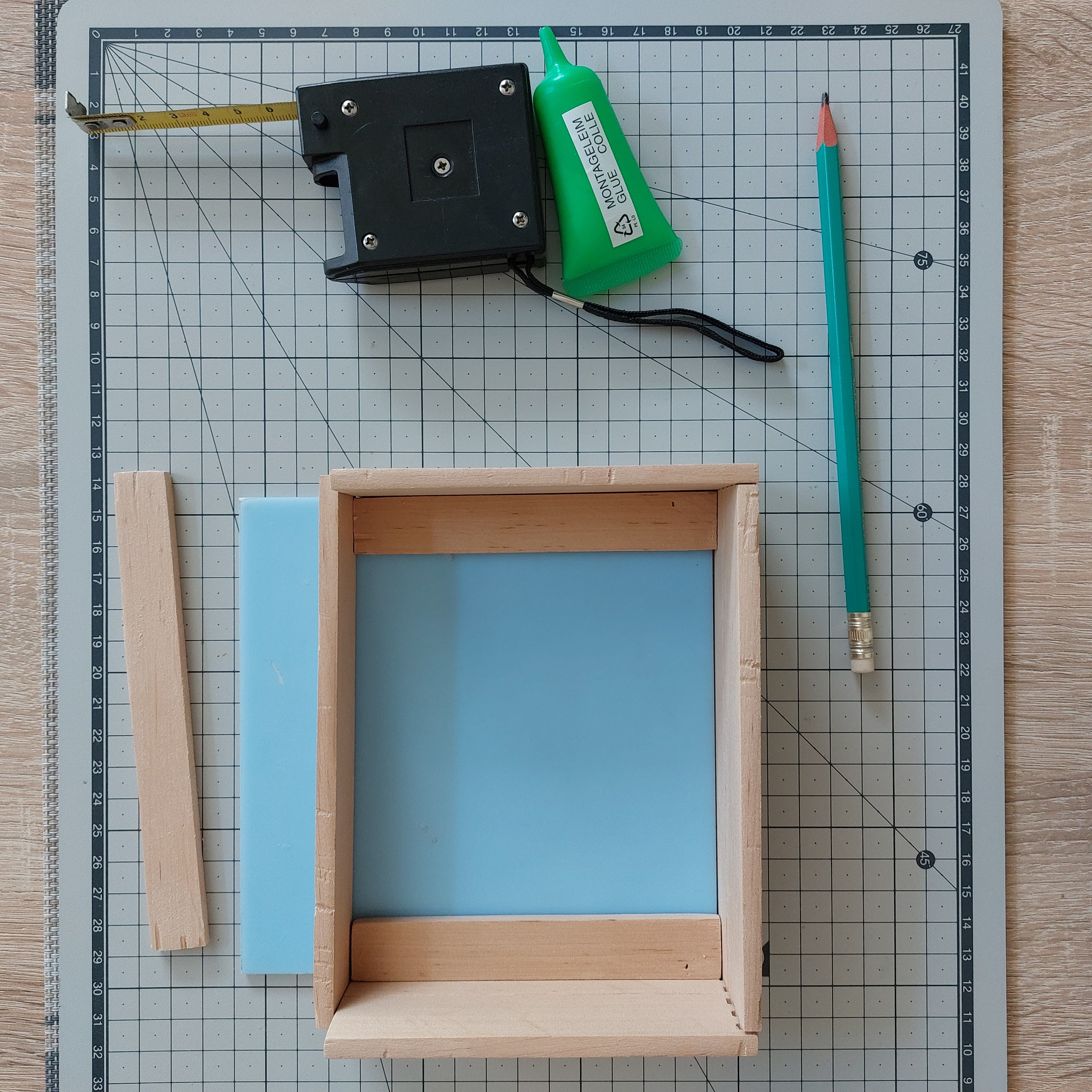
Actual case dimensions are 125 x 160 x 45 mm.
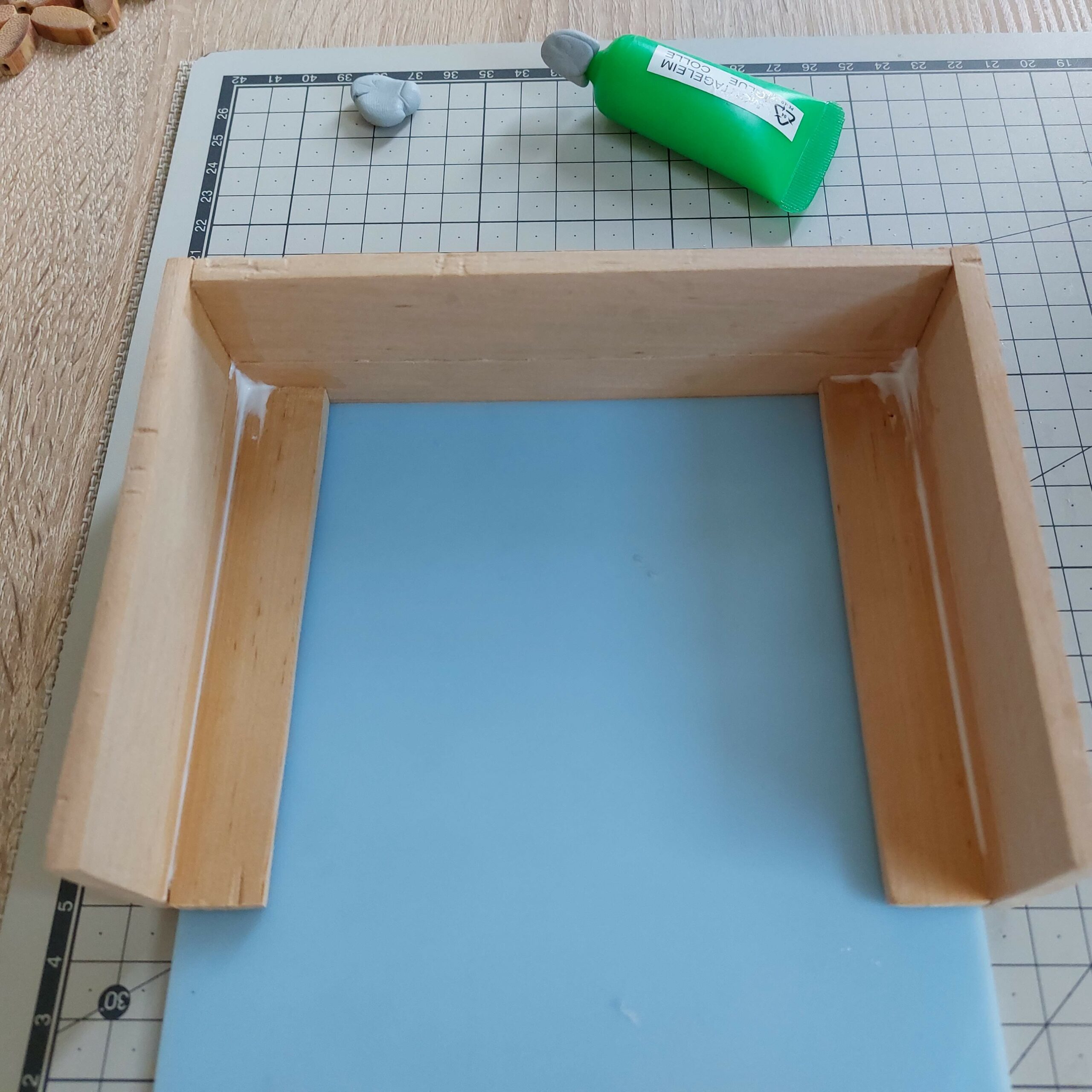
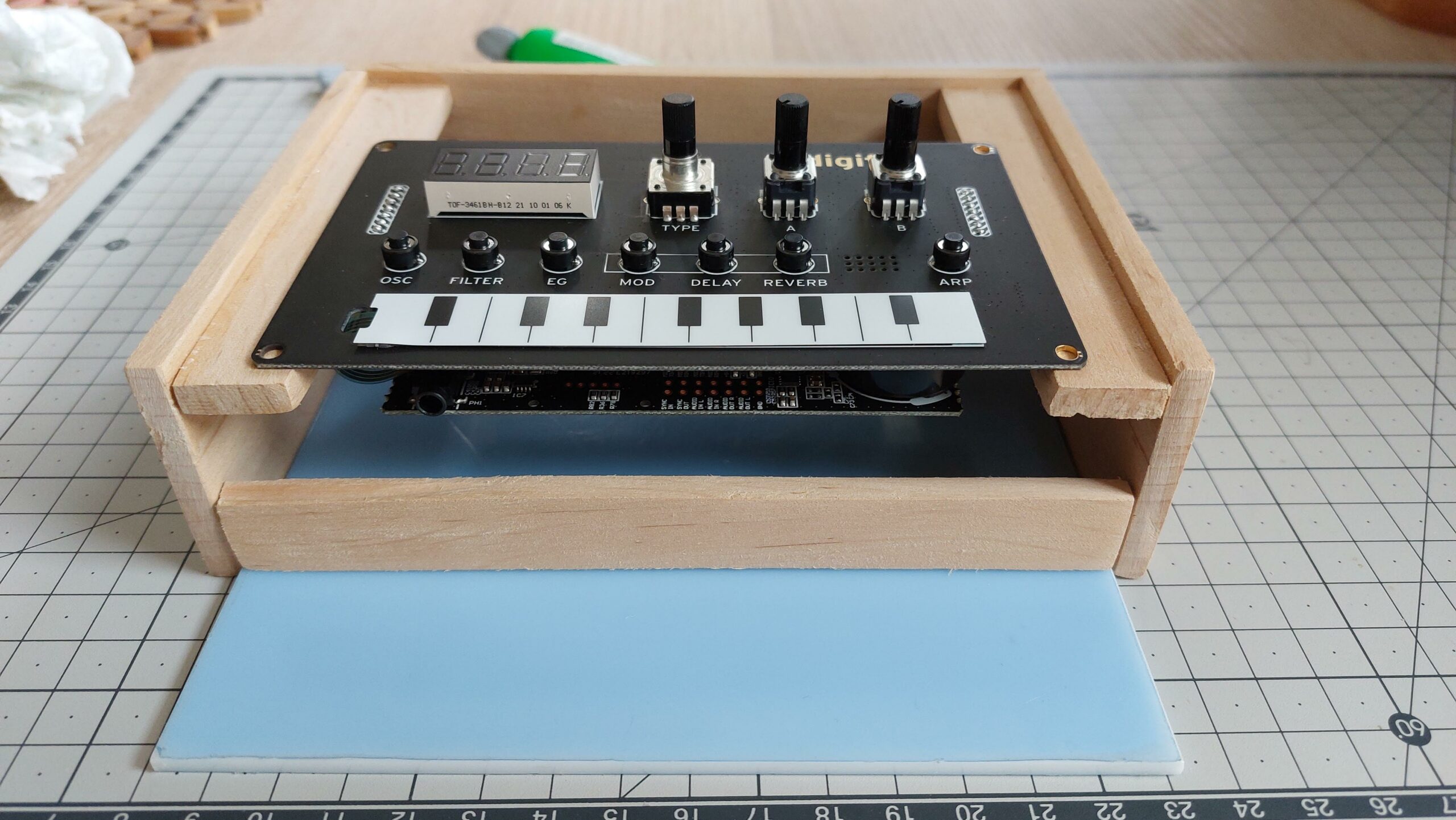
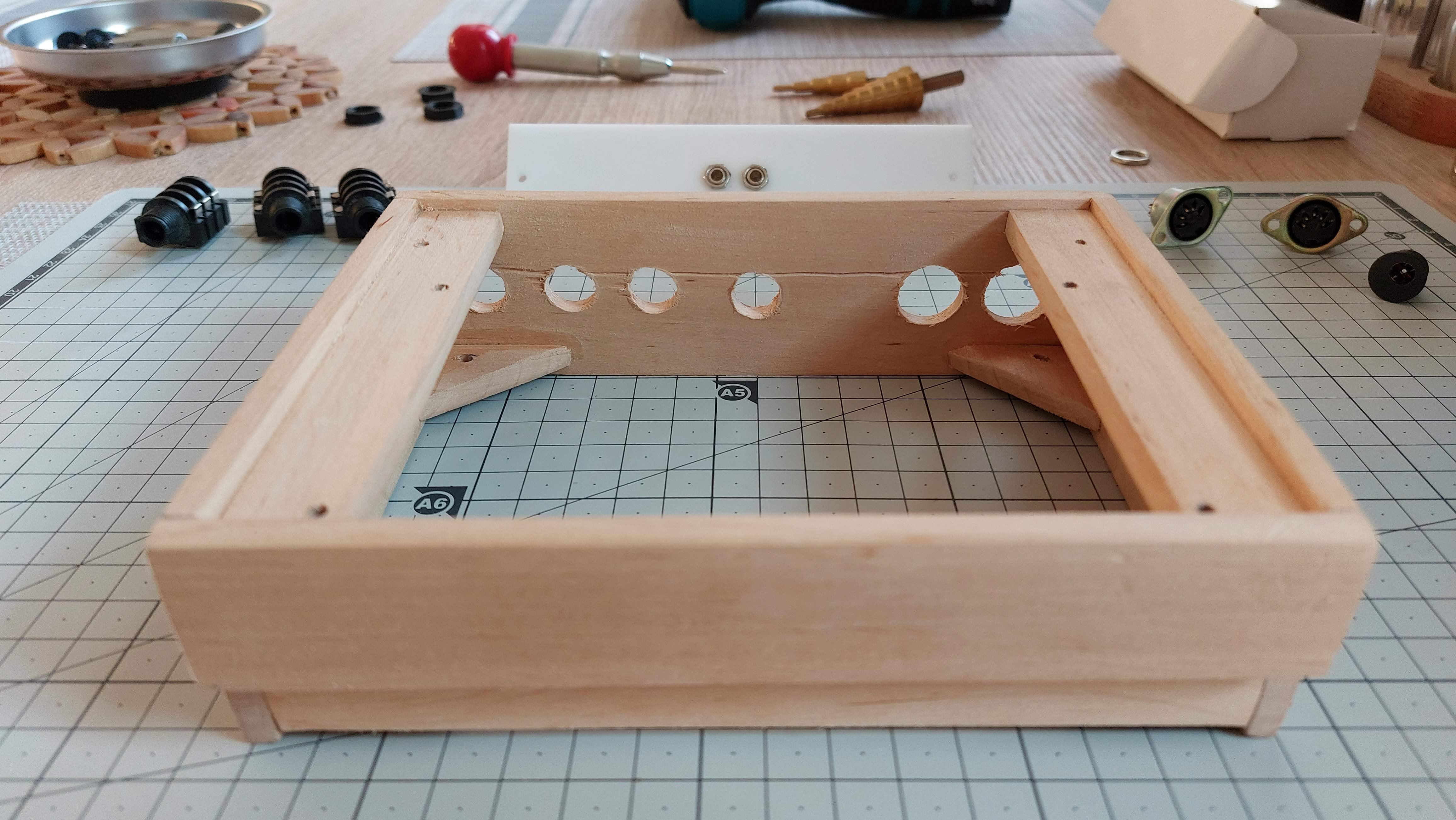
Using wood glue to put pieces together. But first we need to test fit the pcb and mark mounting points.
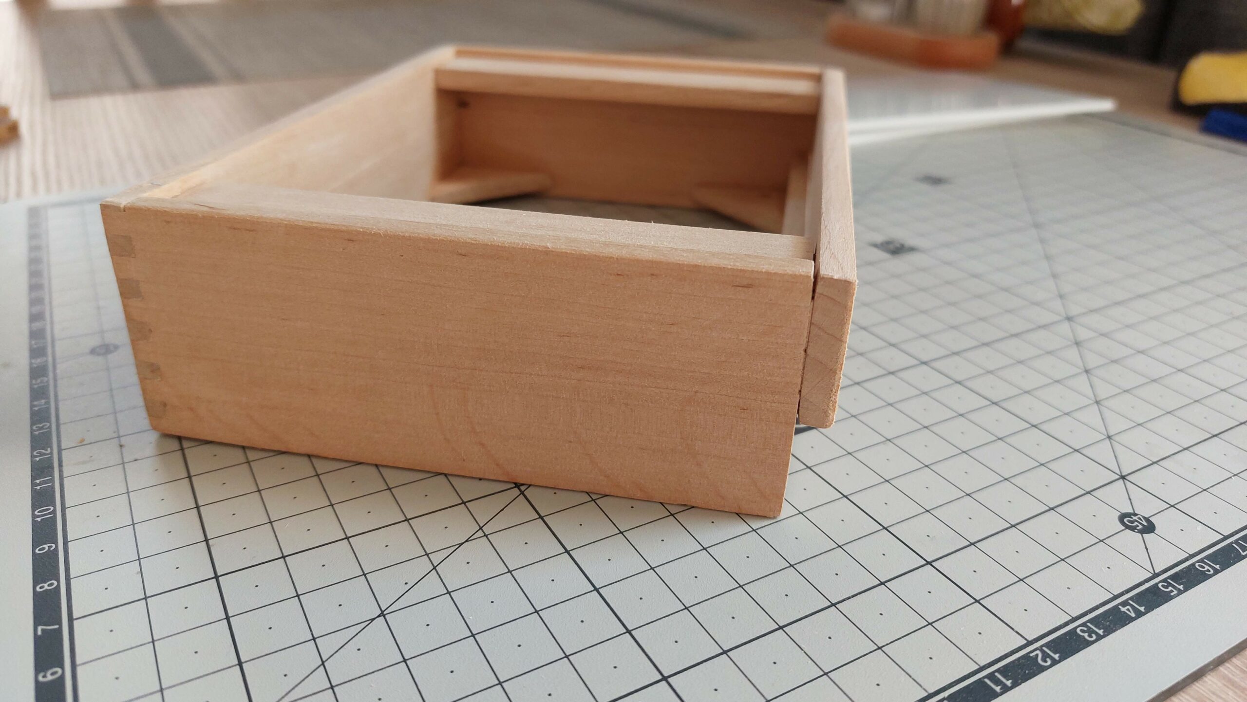
I had two different pieces of wood to make the front side. They don’t have an equal size and don’t fit together so I got the idea to have some sort of piano look like so the top piece is put forward.
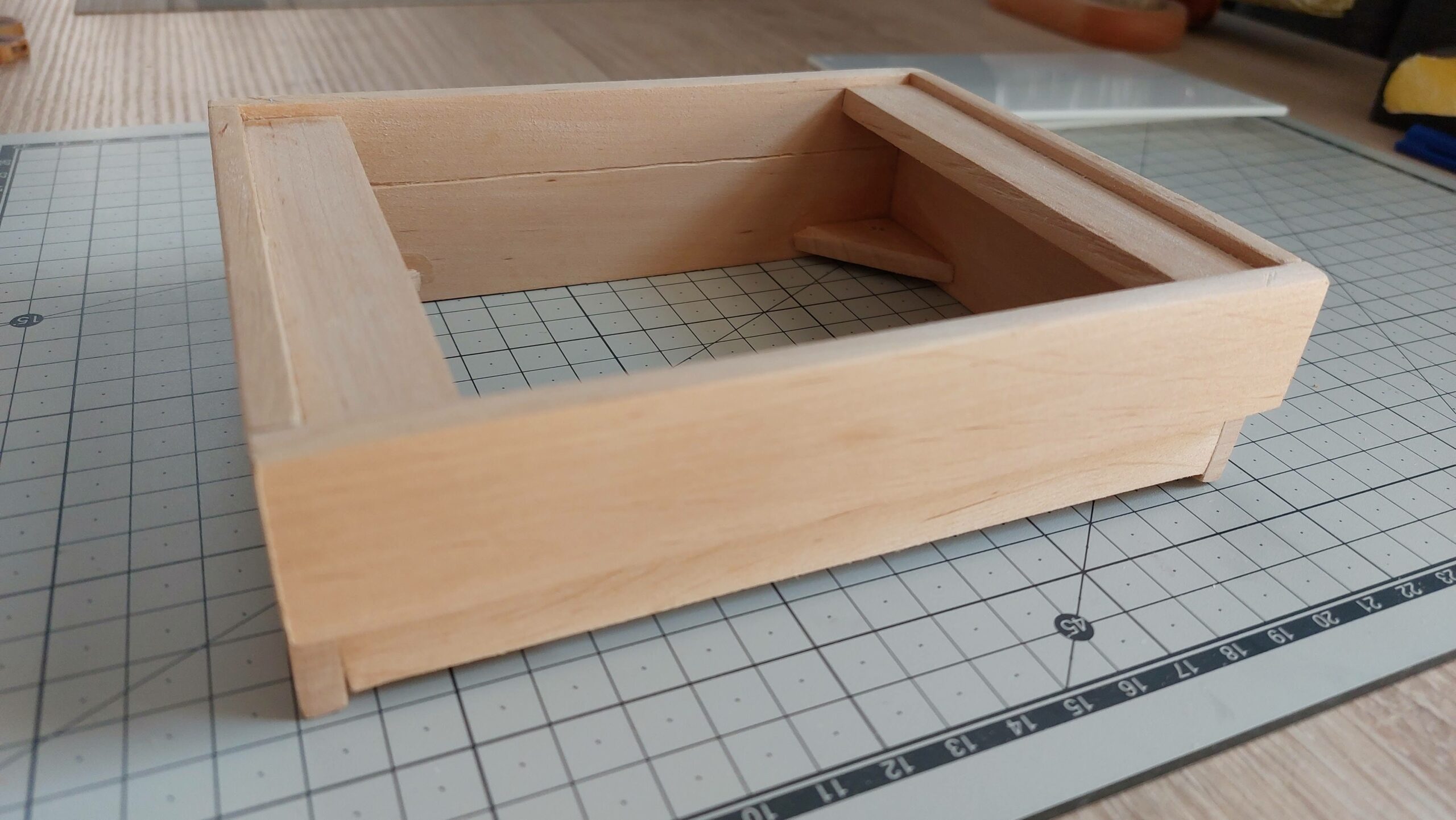
It came out nice!
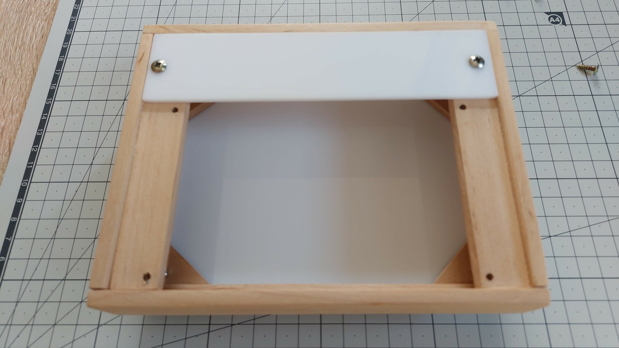
Drilling holes for top panel and bottom feet. Cutting and sanding ABS panel to fit the dimensions.
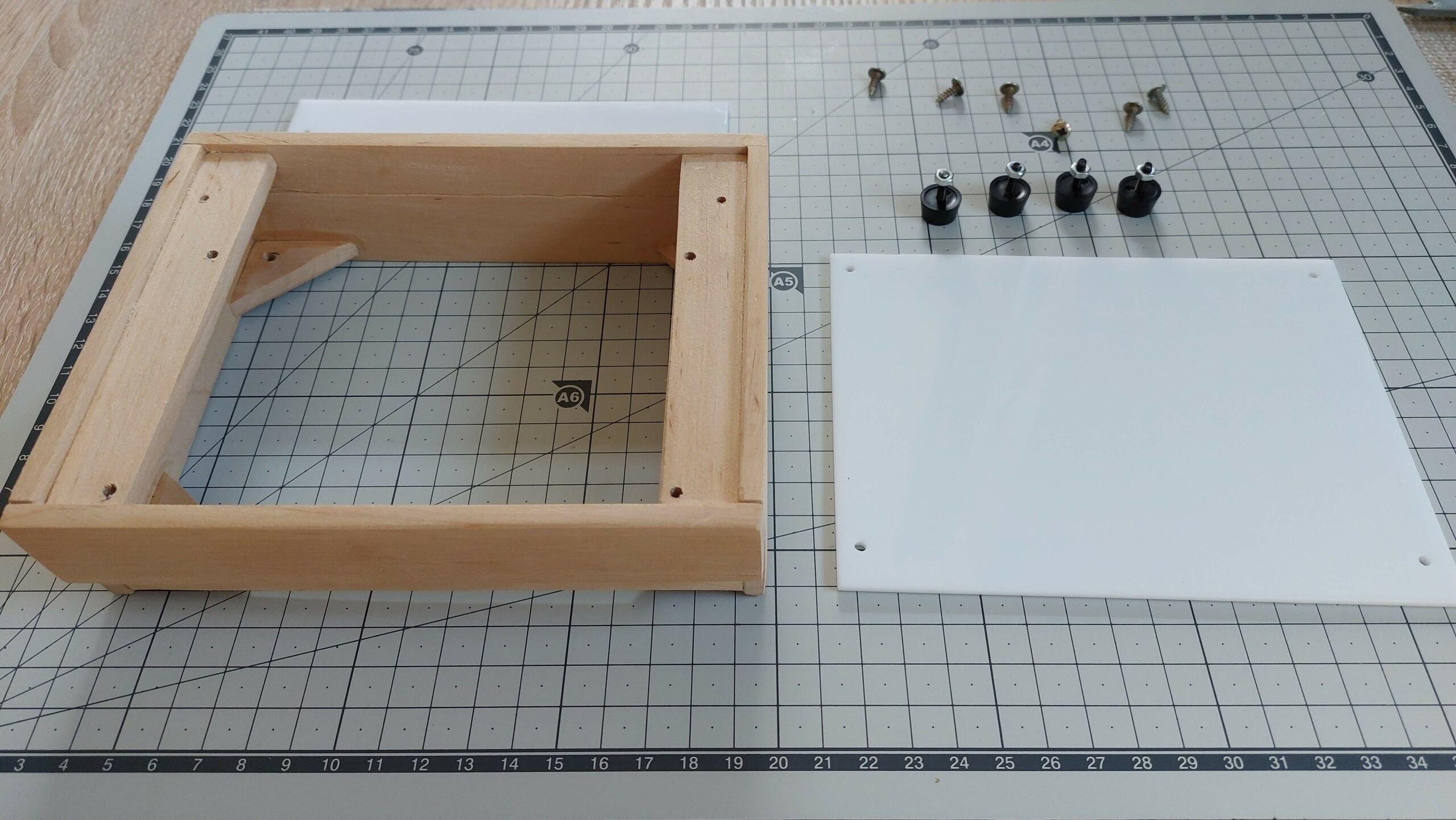
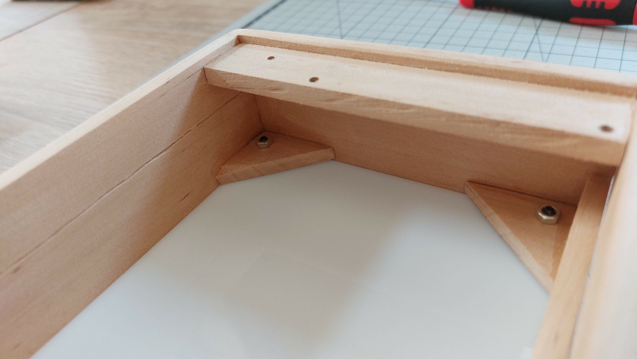
I only had one piece of wood left, so I had to divide it into four corners to keep everything tight and it’s also a base for rubber feets.
Attaching rubber feets to the same M2 screws that holds bottom ABS panel to the case.
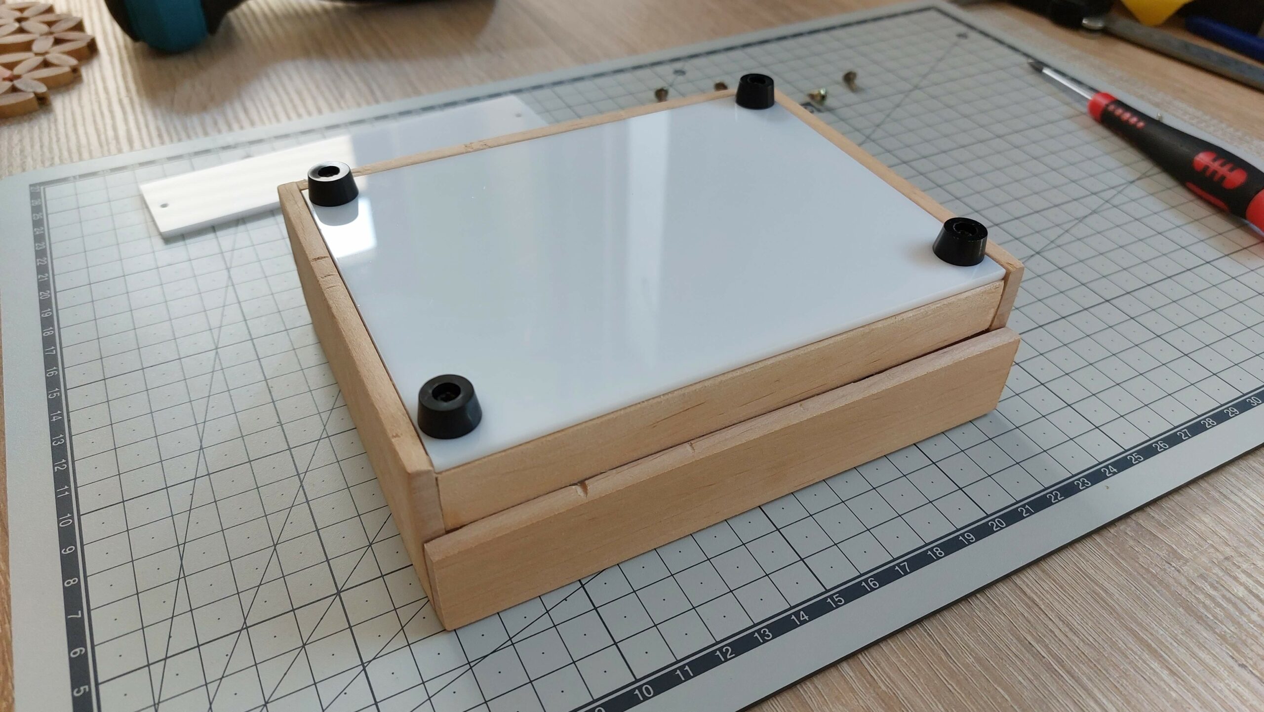
You can notice that front upper wood panel is not even with the small bottom one, but we can not see that 😀
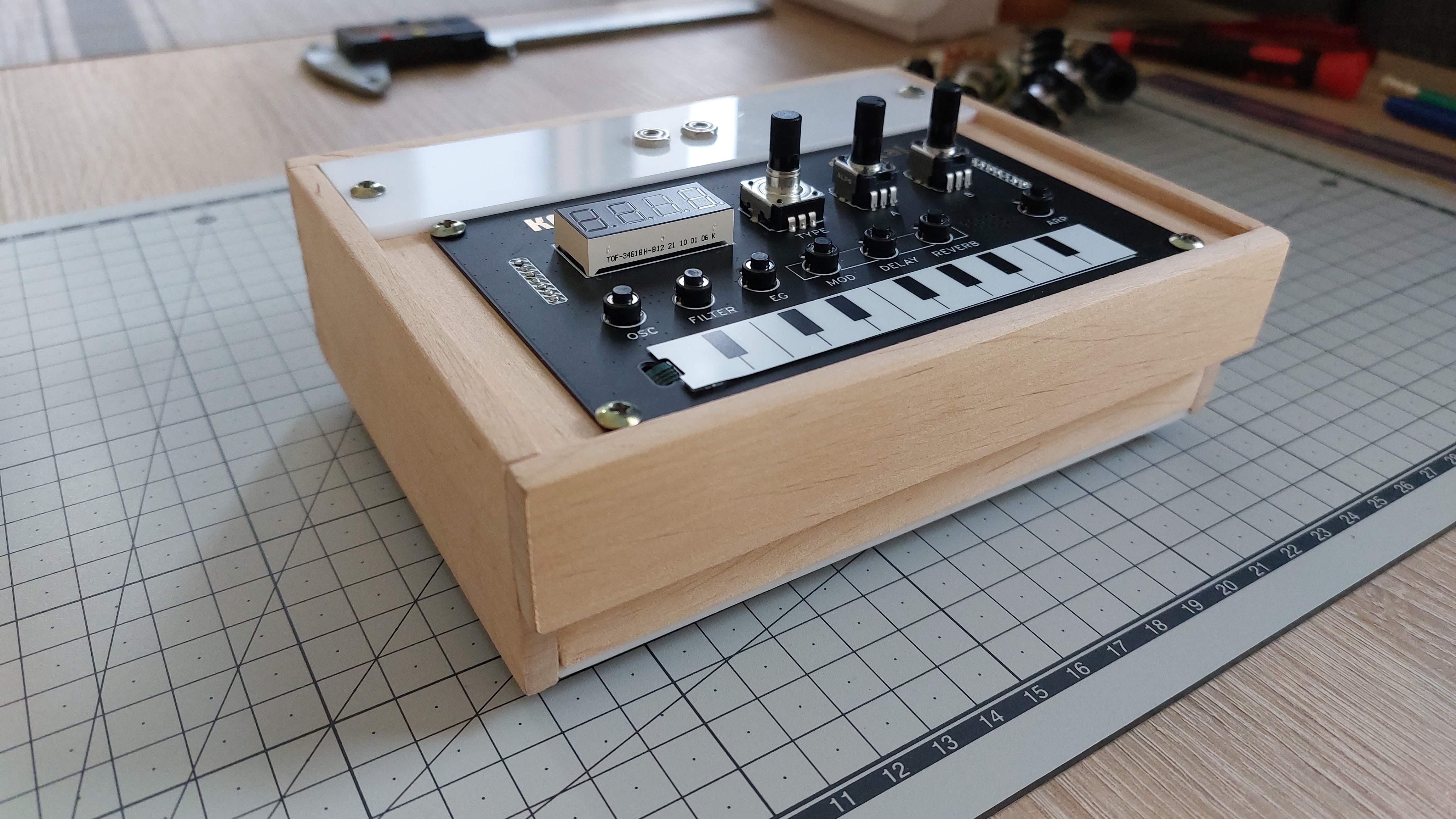
Test fitting panels and NTS-1 front face pcb.
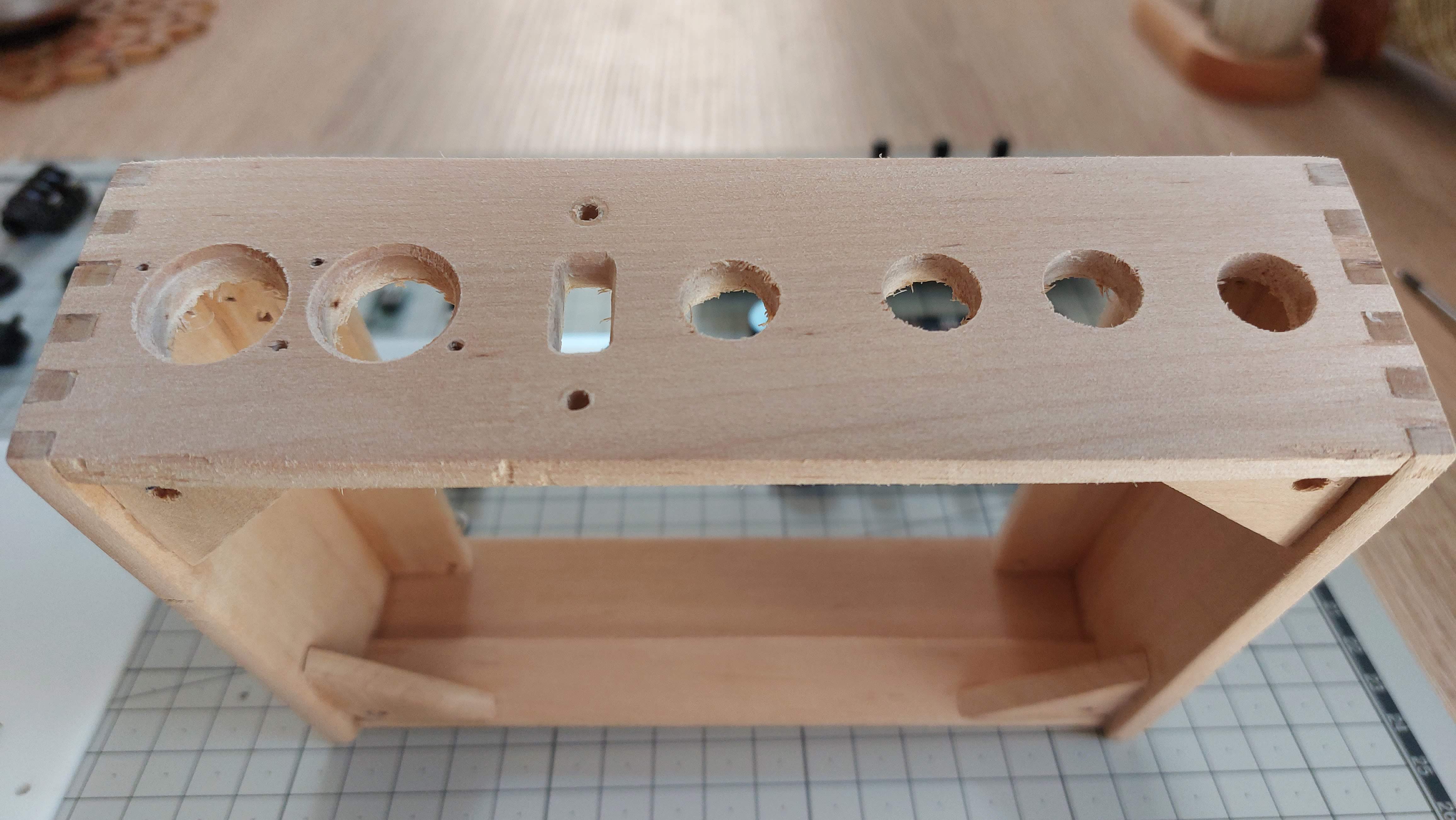
Now we need to drill bigger holes for our input and output sockets and connectors with step drill bit.
The hardest part is to file down the square hole for polarity switch.
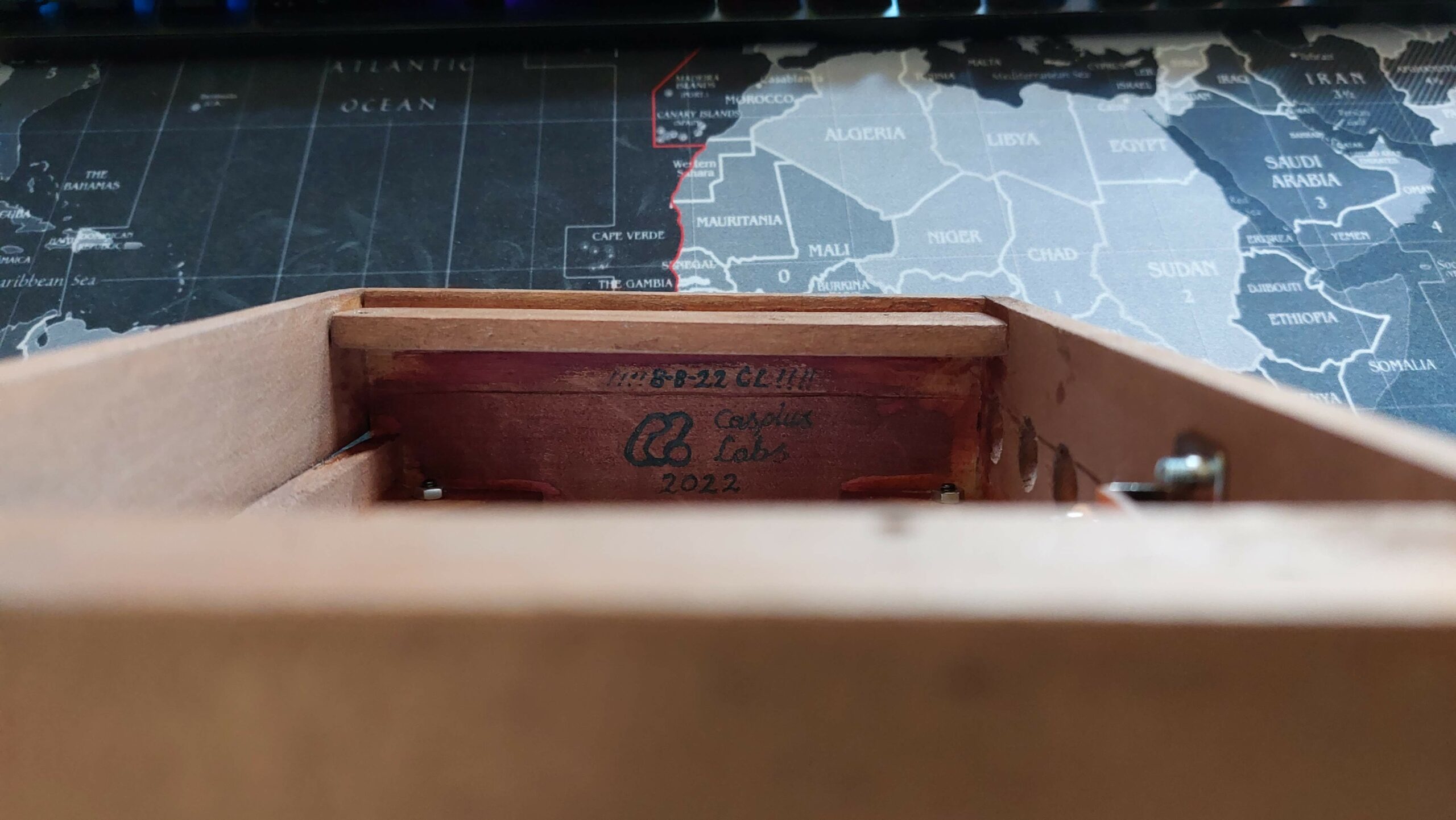
Added some signature 😀 I actually finished the case on 8.08.2022.
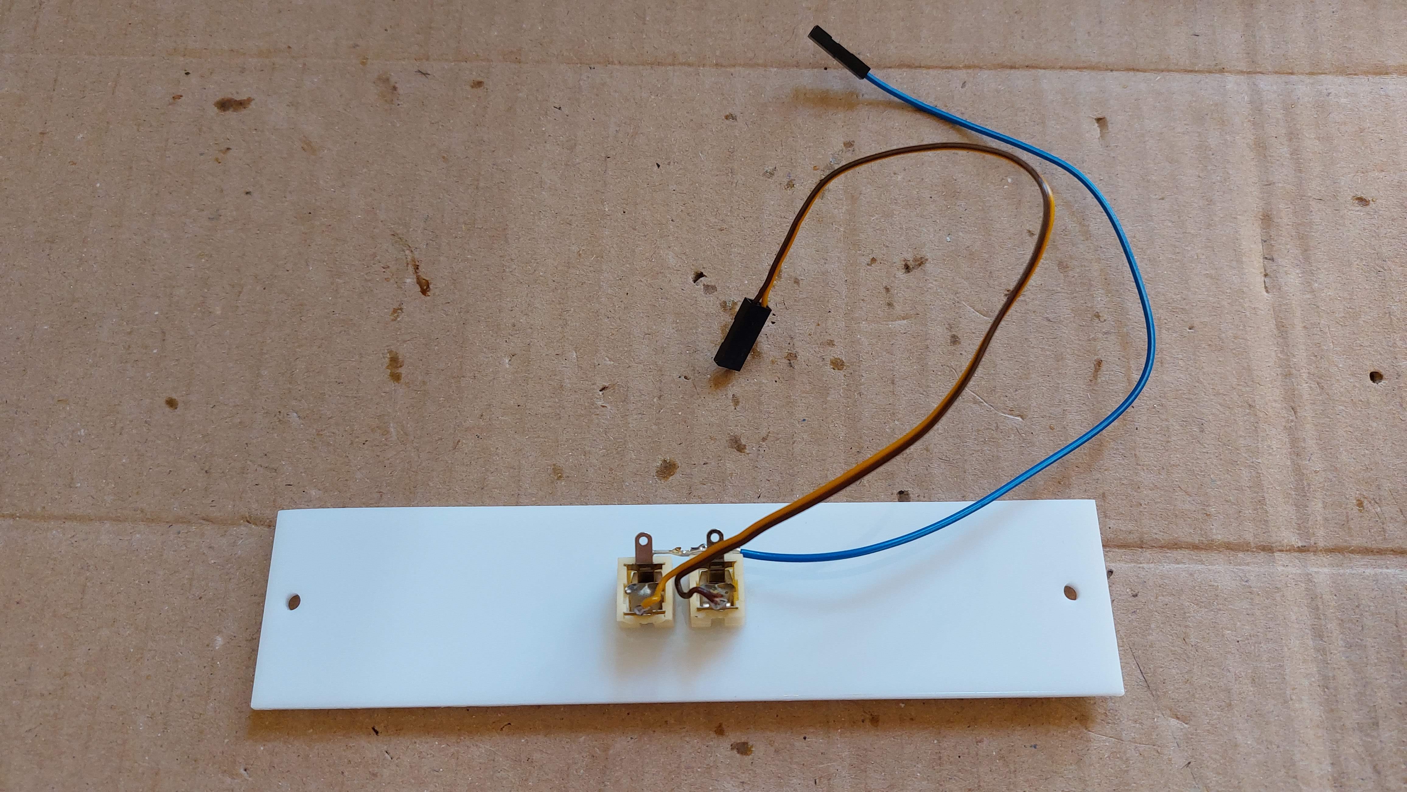
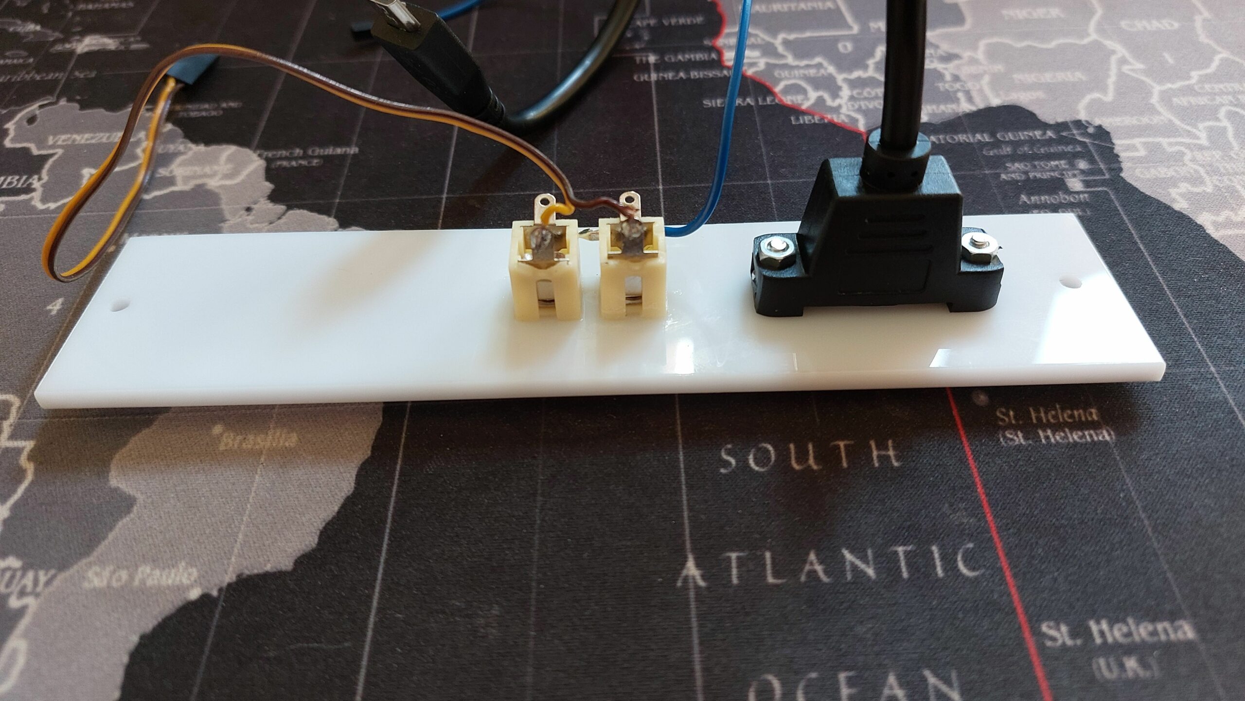
We need to drill holes in the top panel and insert 3.5mm jack sockets for Sync IN/OUT.
Again some hard work with round file to make hole for USB socket.
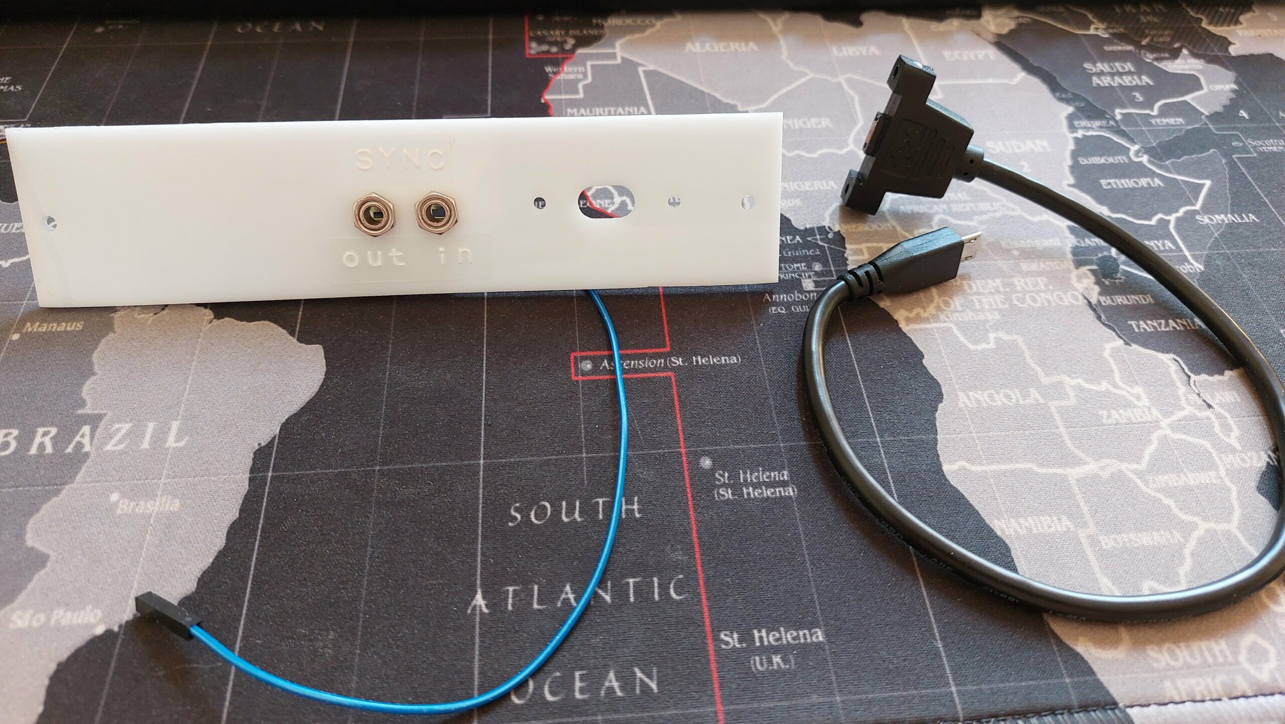
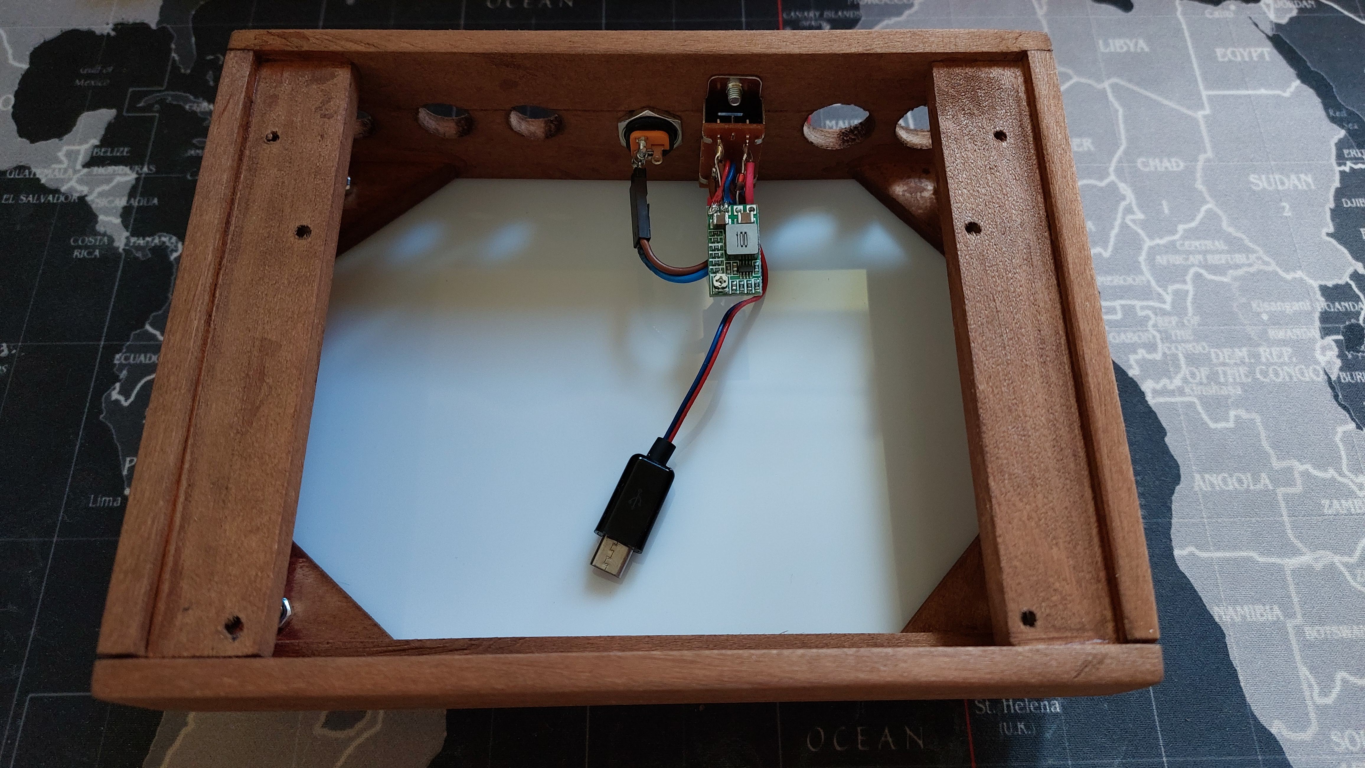
I’m using Micro USB panel mounted extension cable connected to the Synth, to be able to update firmware and upload some new oscillators or effects.
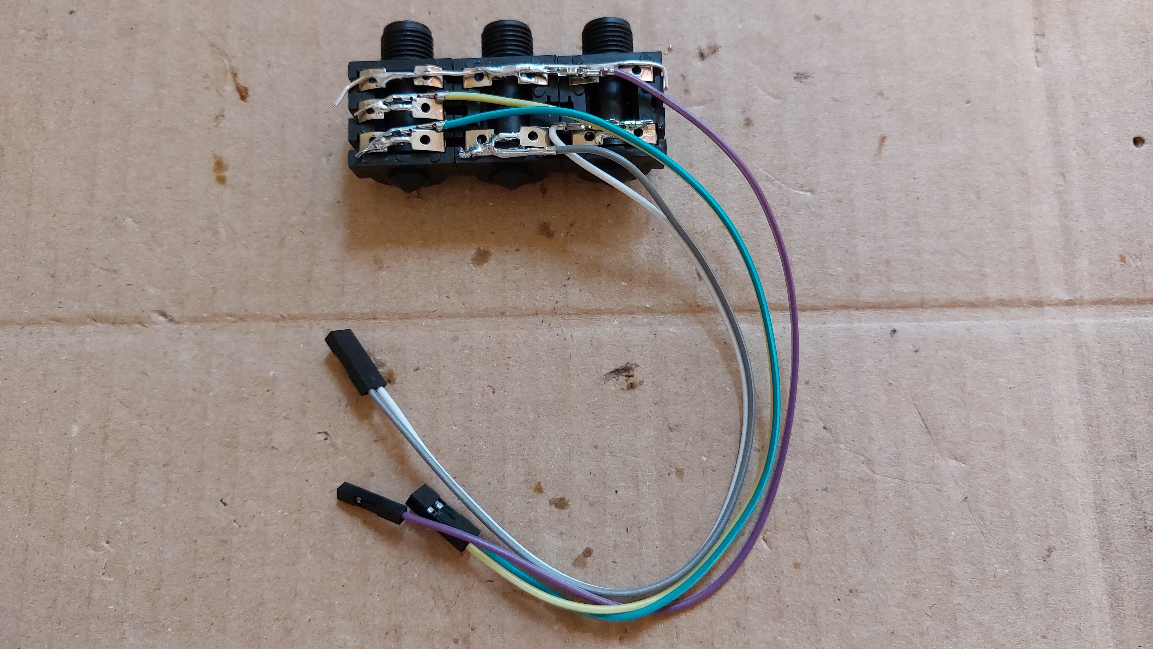
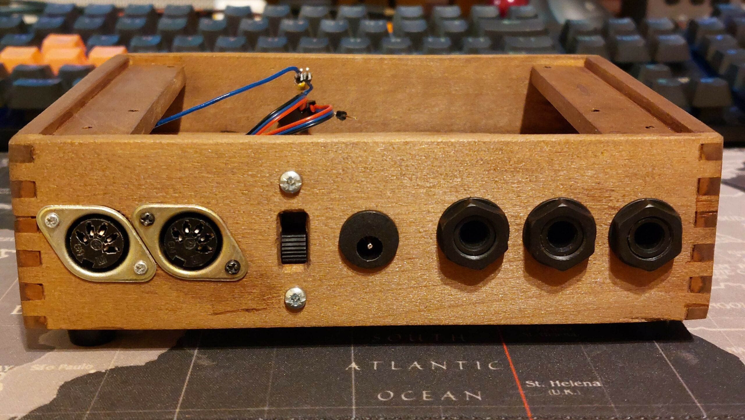
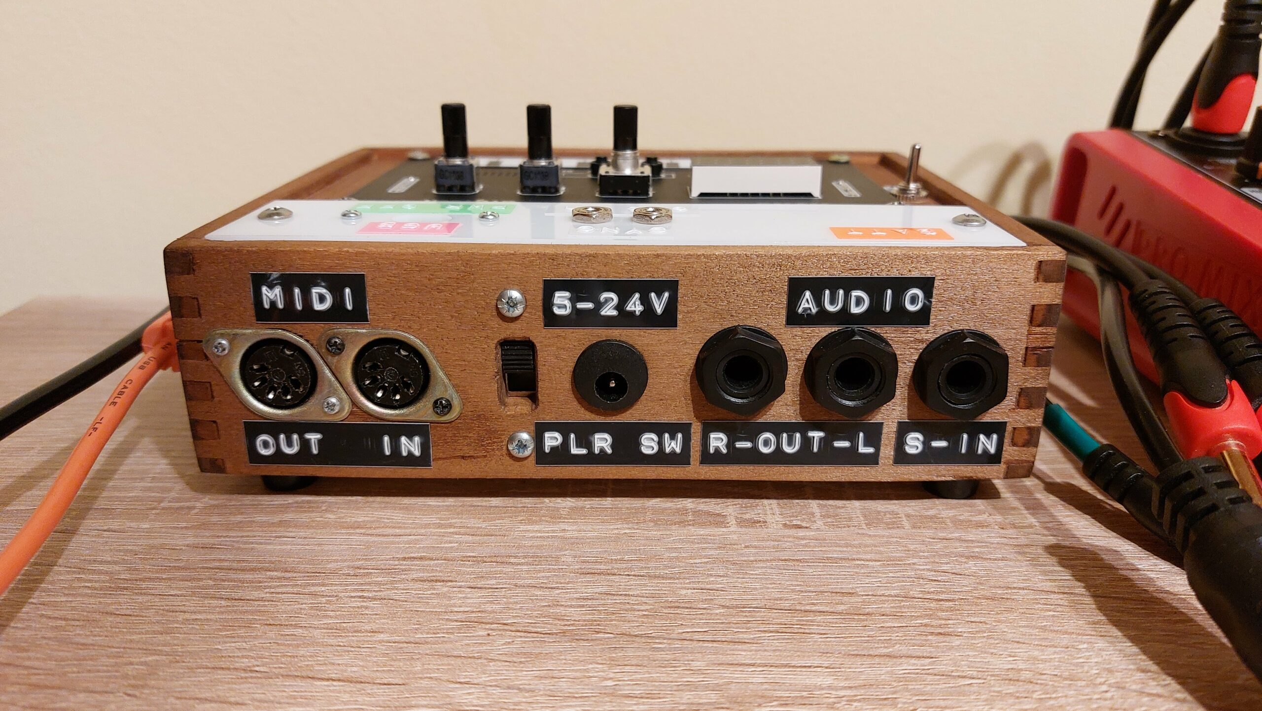
Now we need our audio IN and OUT sockets for 6.35mm jacks. Im using one stereo socket for audio IN and two mono sockets for audio Left and Right OUT. You can switch them around if you prefer to have two mono Inputs and one stereo out for headphones. Future idea here is to add some switch to do that without opening the case 😀
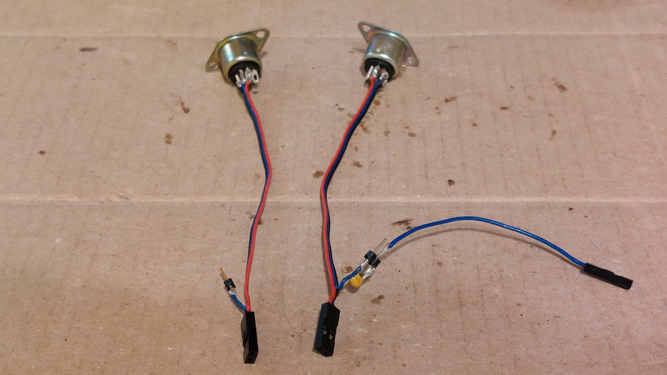
Now Midi IN and OUT are done on two Din-5 female sockets. I’m using here three wires for data pins 4/5 and middle pin for the GND. But GND is connected only to the Midi OUT socket. That way you can switch socket position in the case. Notice that there is 100nF ceramic capacitor on Midi GND, but it’s not necessary. There is also female pin socket at the end of the wires to disconnect or switch around data pins on the synth pcb.
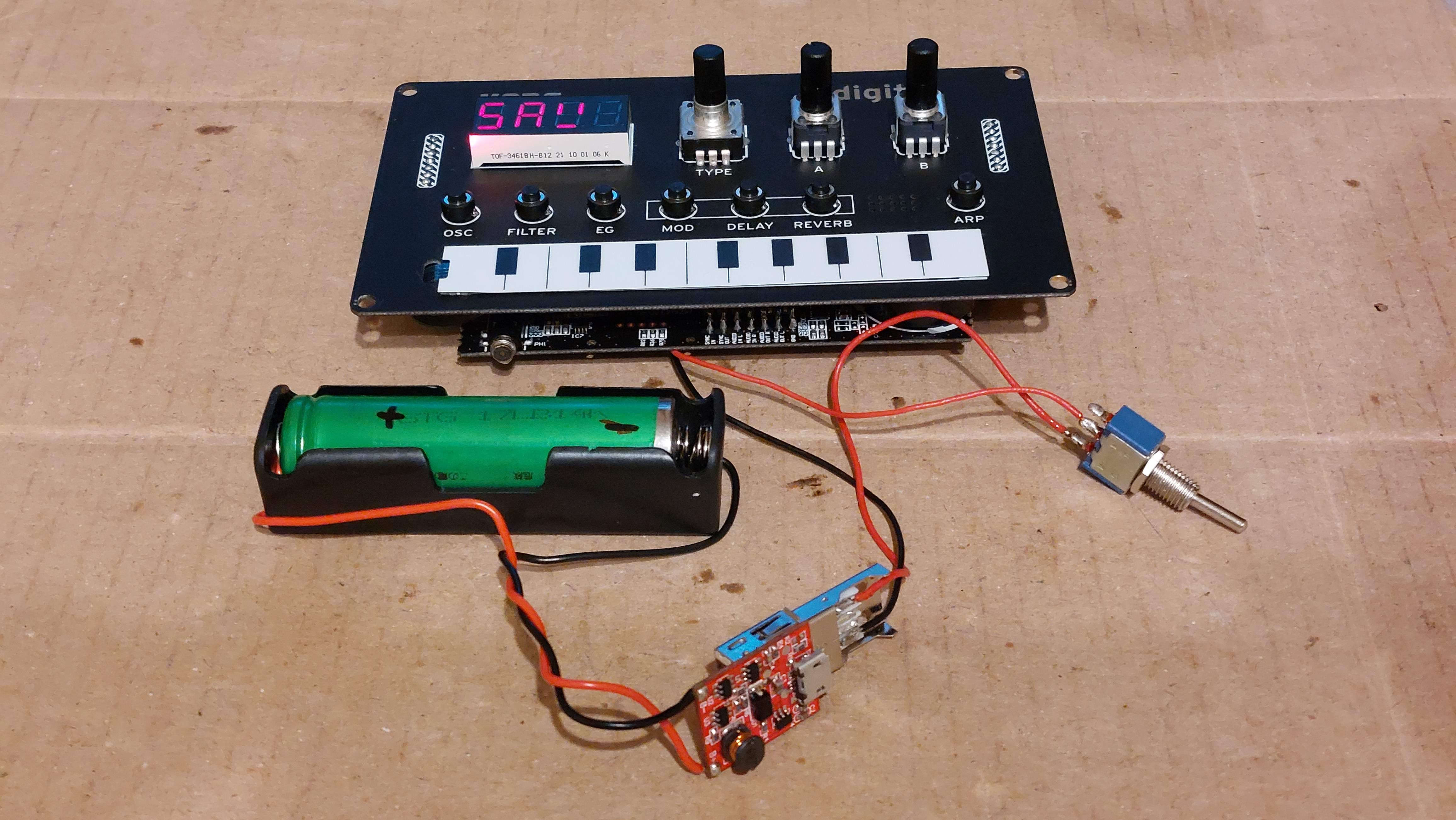
We also need our power/battery circuit wire with a switch to turn NTS-1 ON and OFF. It has pin connector and USB type A socket so it can be detachable from the synth pcb.
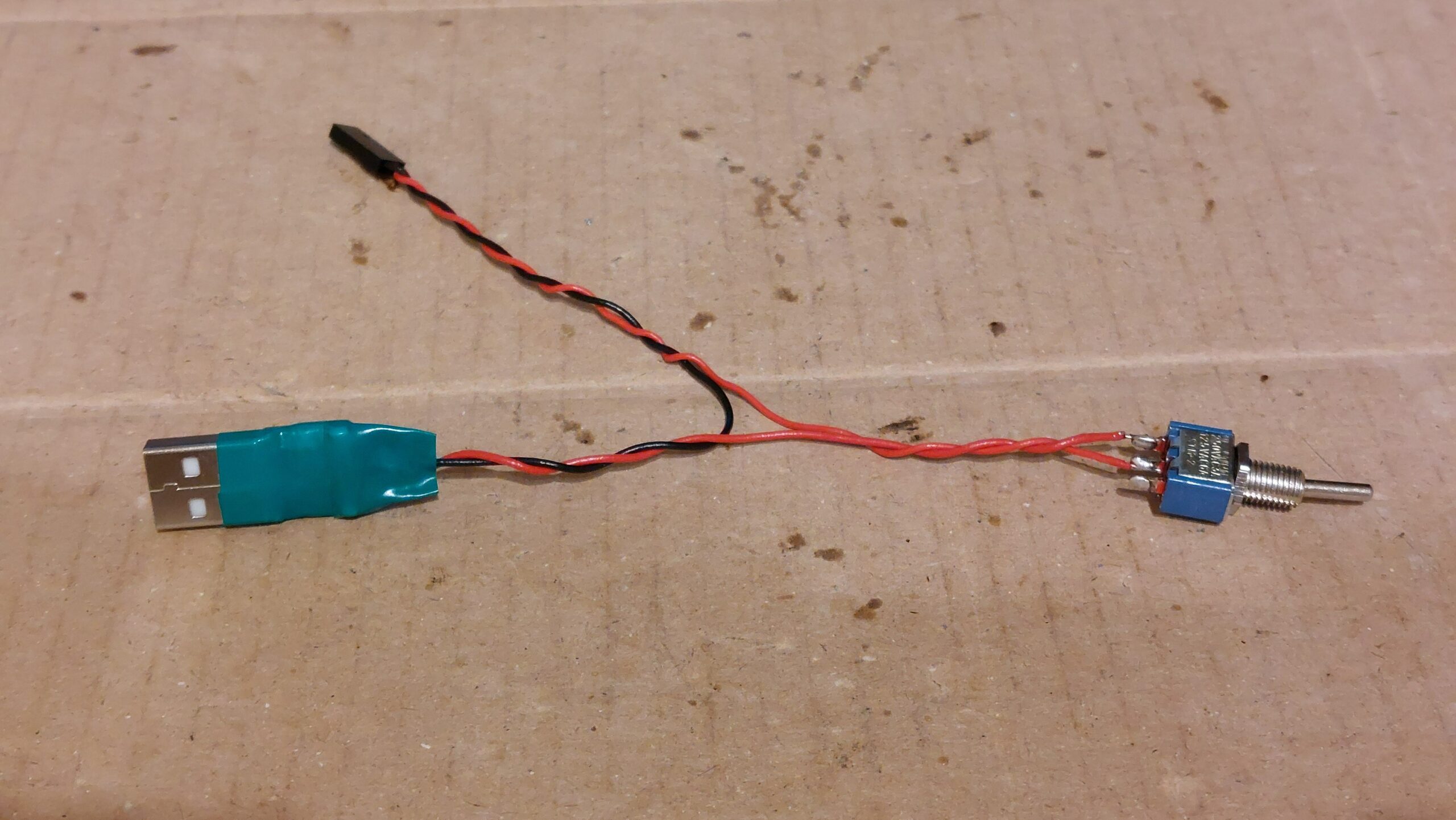
As for our power circuit I’m using HW-613 step-down converter that can take from 4.5V up to 24V on input and converts it to steady 5V 2A on the output, that means we can use any power supply brick or wall wart.
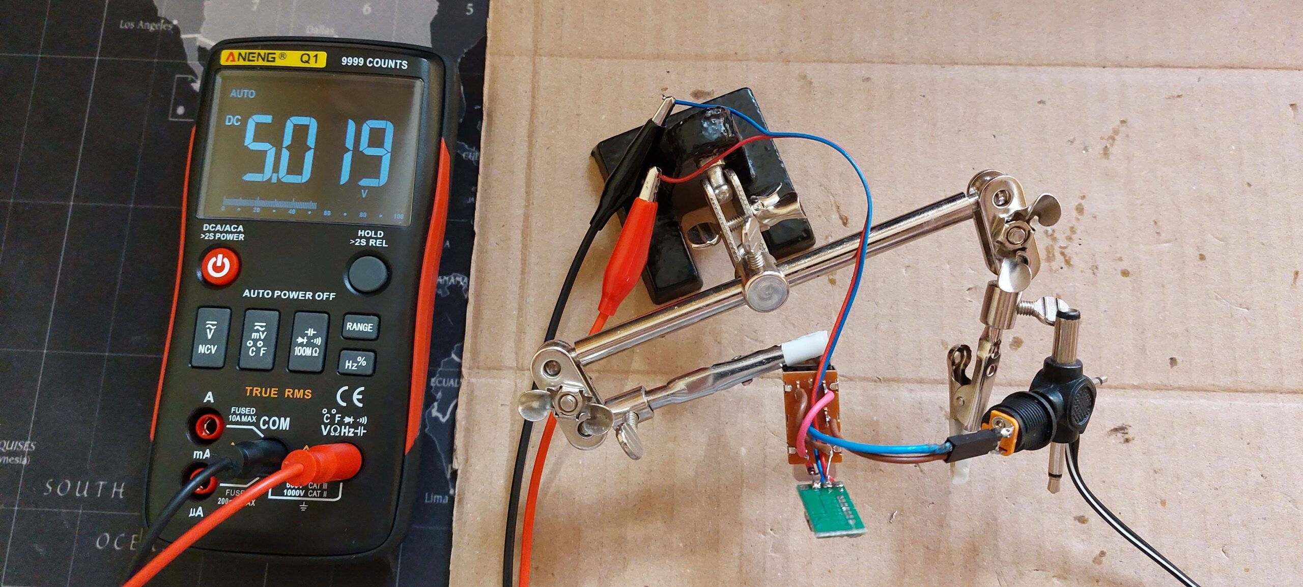
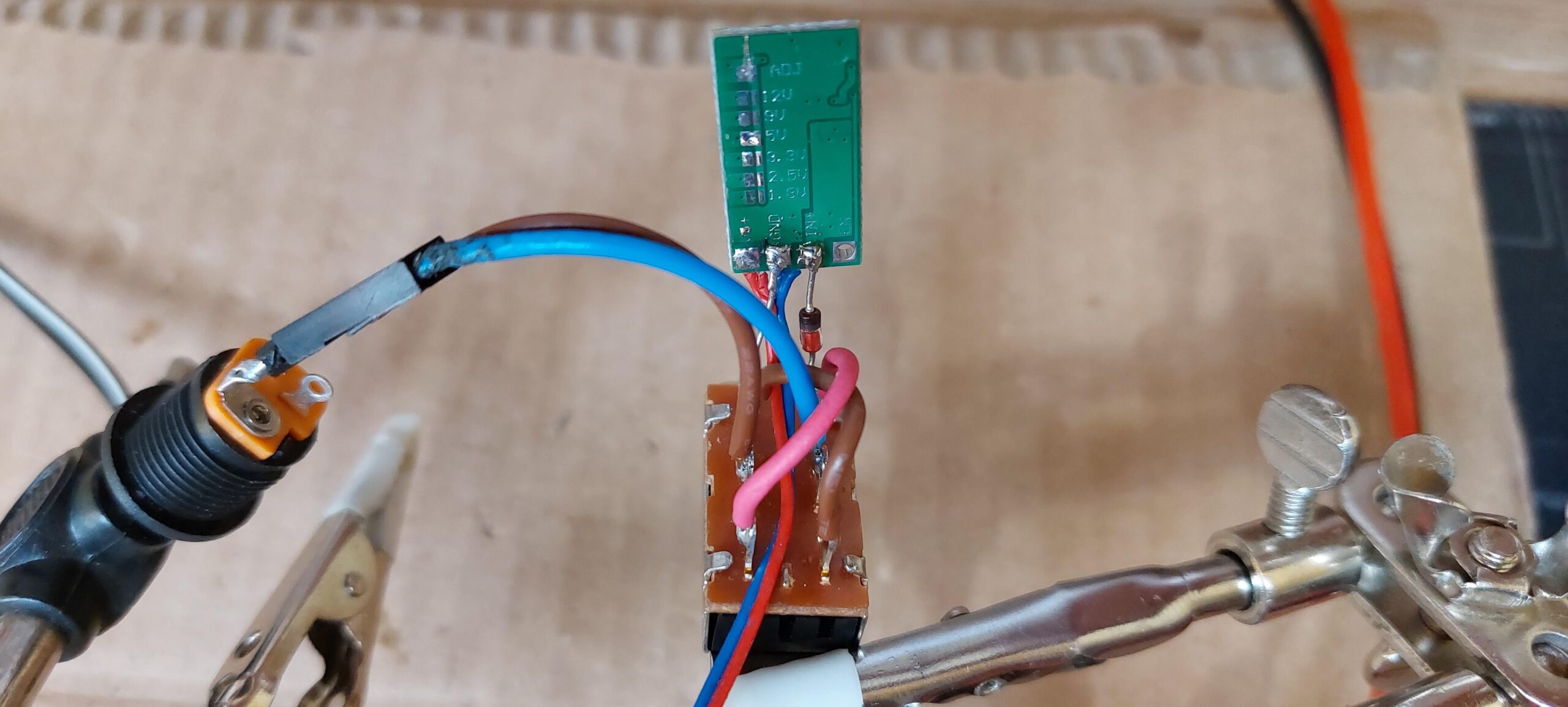
I’m also adding polarity switch with a protection diode to extend the variety of power supply options 🙂
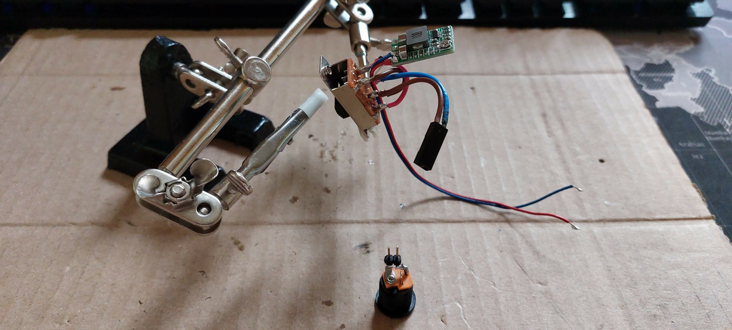
This step-down module can be setup for different fixed output voltage by soldering corresponding 12V, 5V, 3.3V, 2.5V, 1.8V pins. Neat stuff!
Interesting part of this project is that if we want to use our external audio out sockets we need to cut of build in speaker. Unfortunately the non destructive way to do that is to plug something in the original stereo output socket due to the mechanical contacts inside.
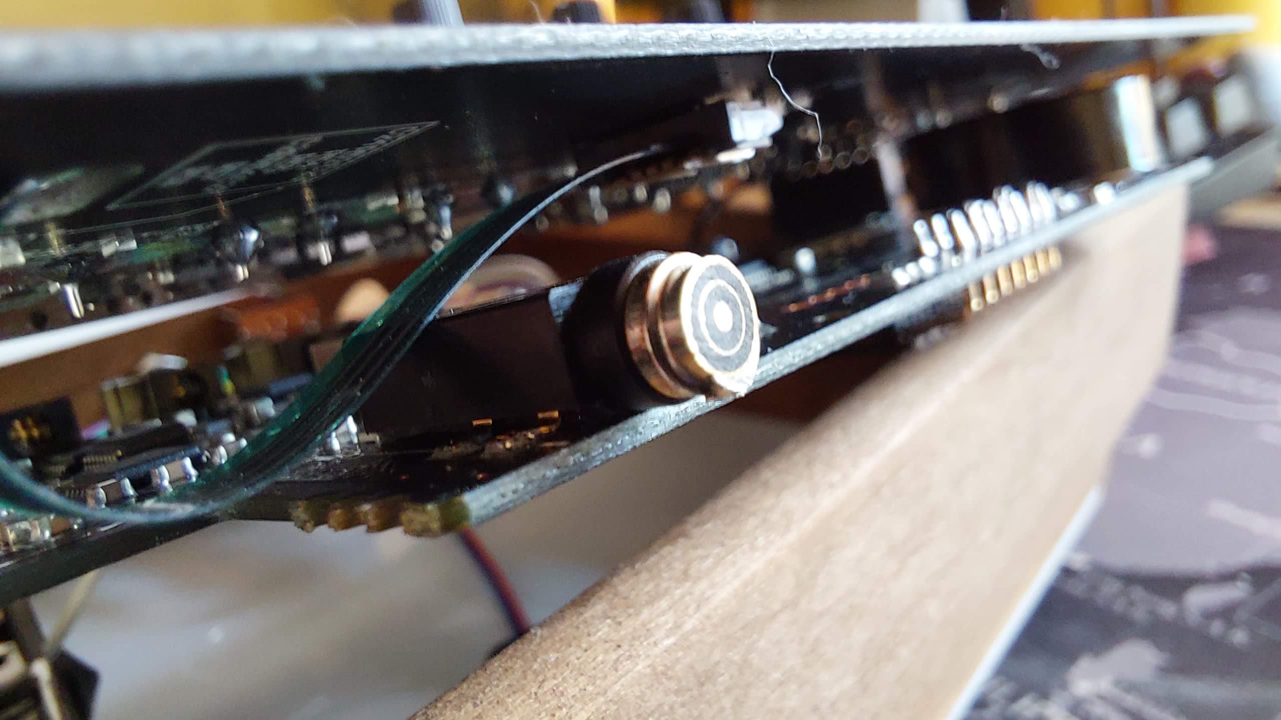
To do that I’m using old headphones plug that needs to be cut as much as possible to hide almost full inside the socket.
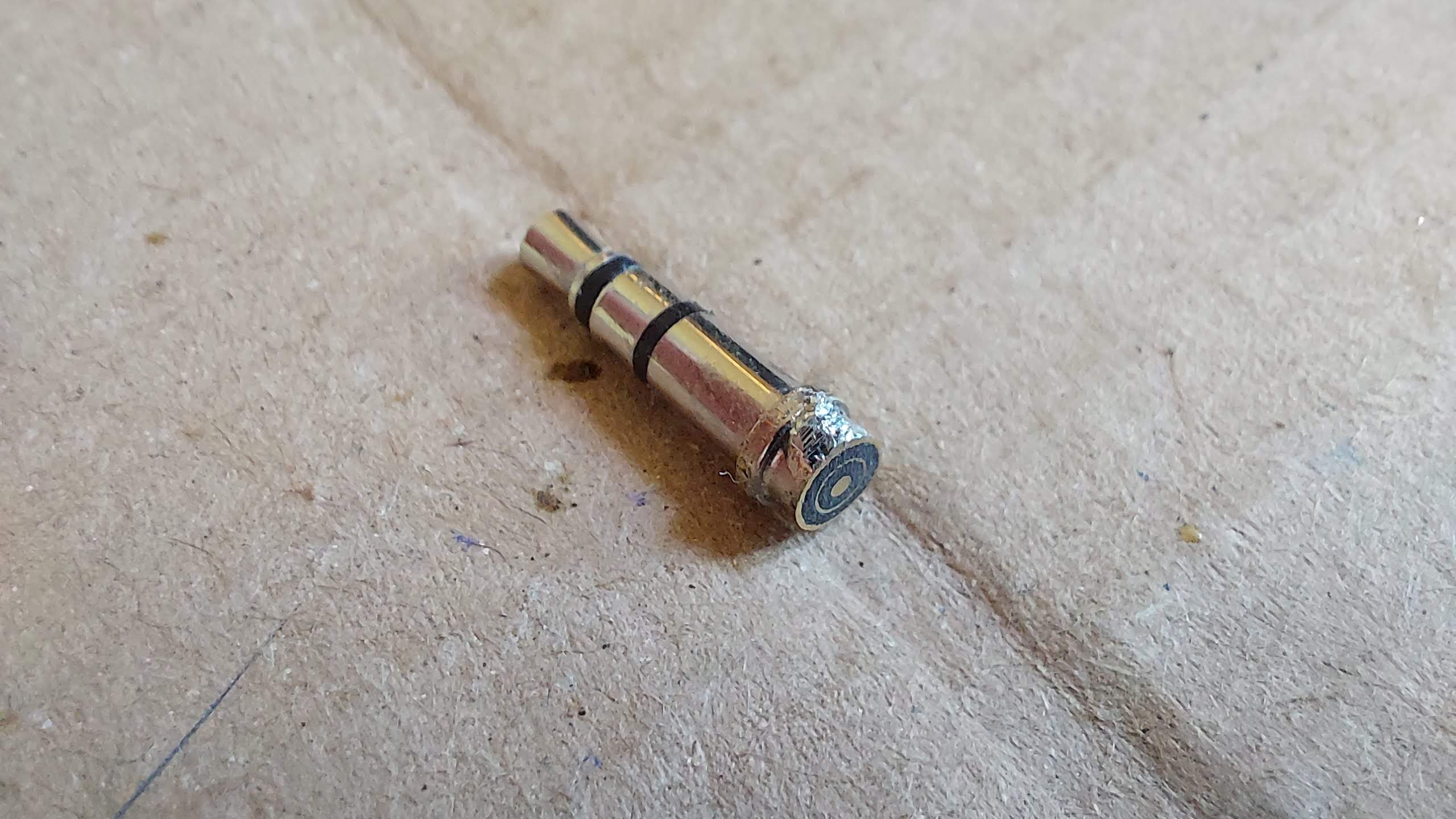
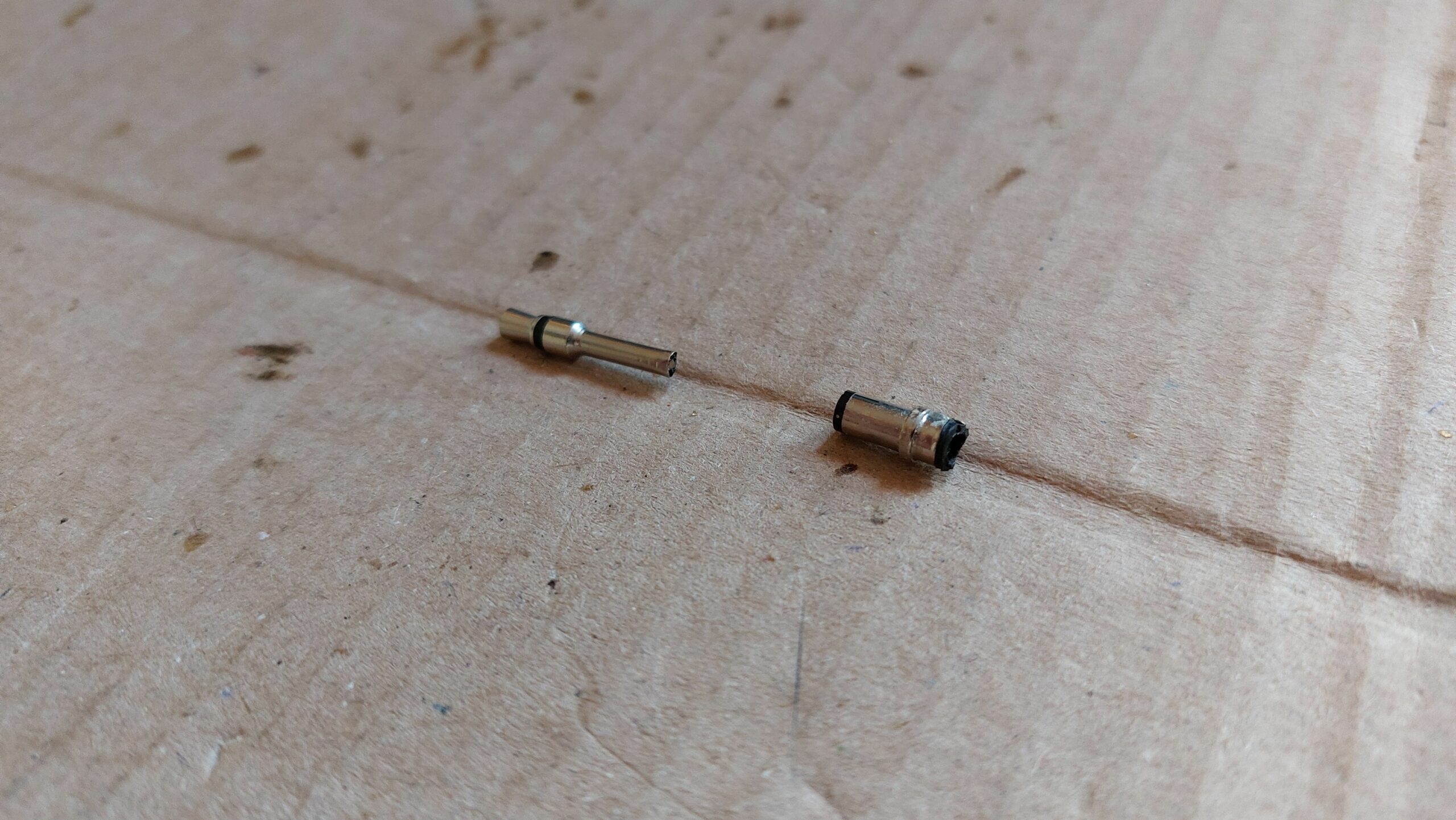
But if we cut it too much it can break to two pieces, and you wouldn’t be able to pull it out of the socket. We need to glue them together to prevent that.
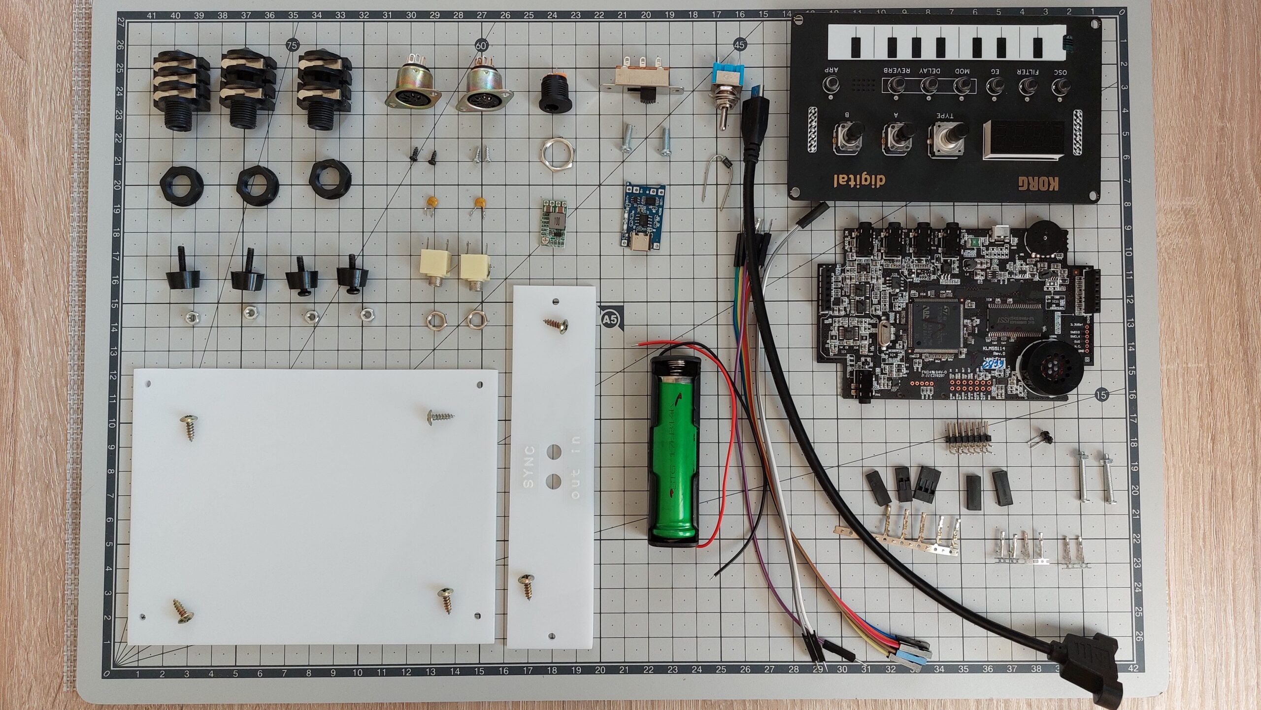
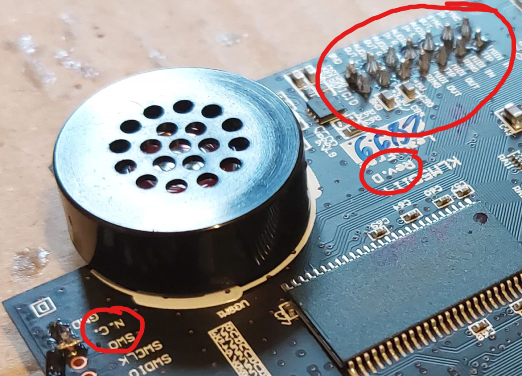
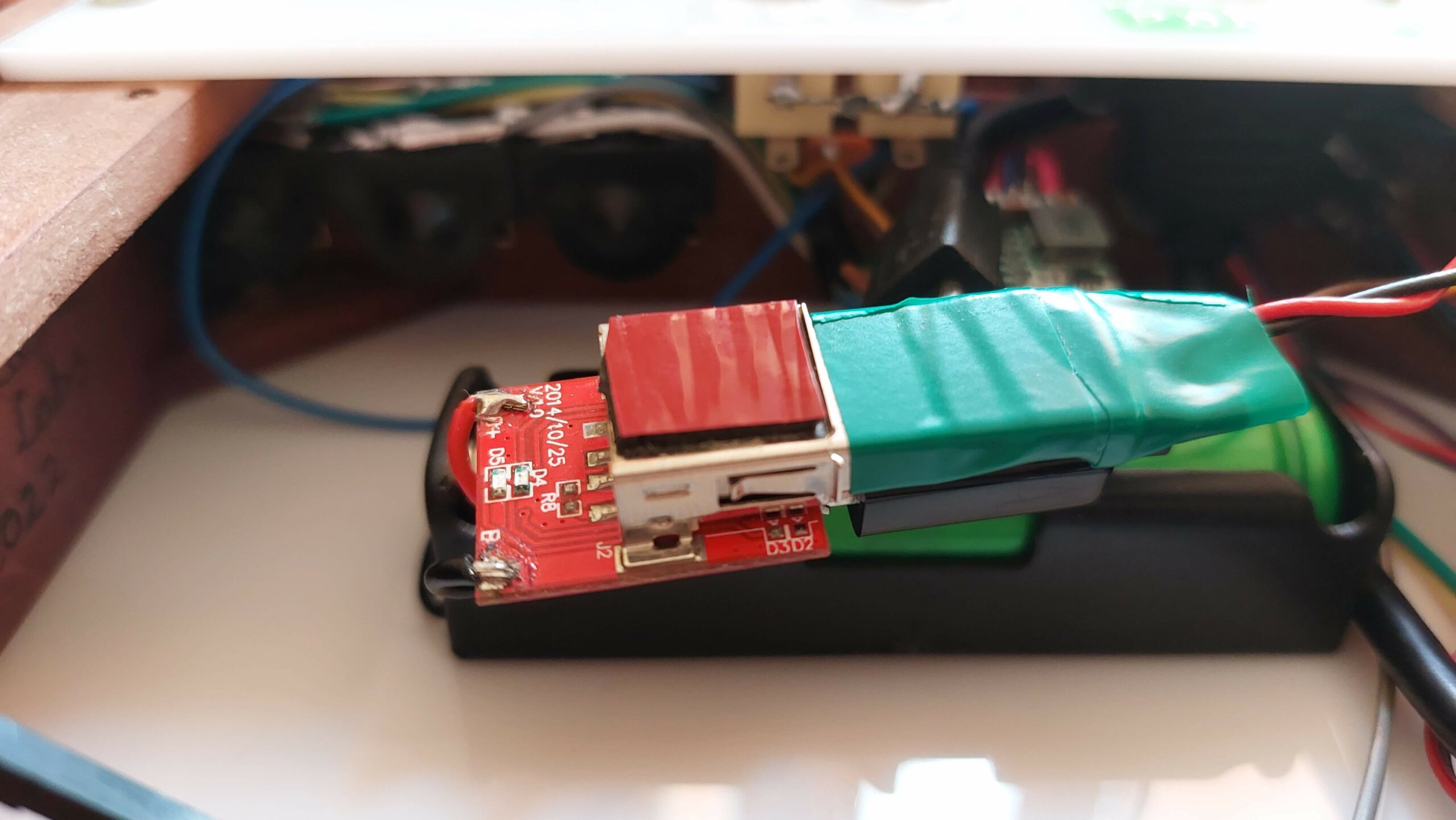
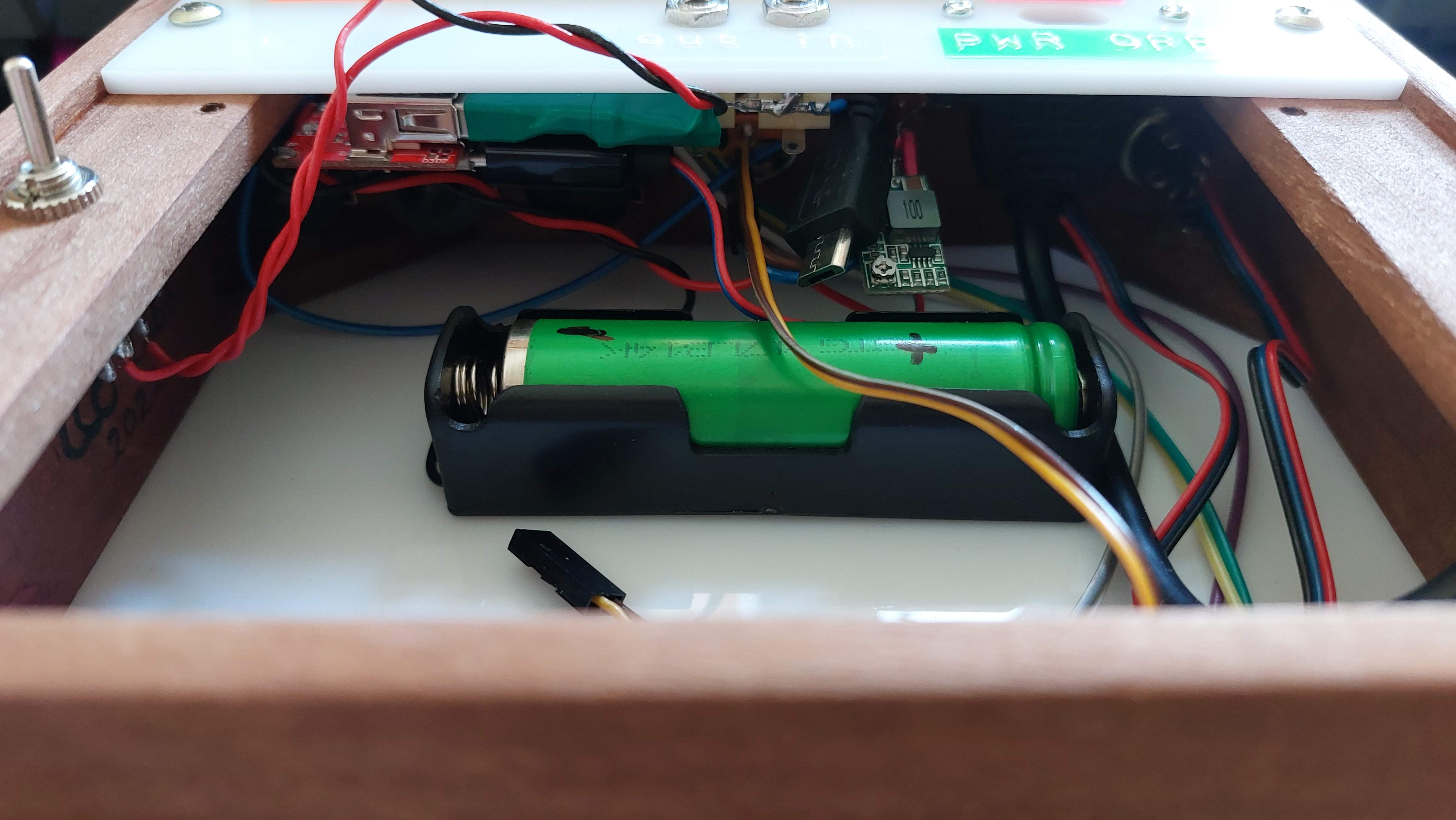
Now how to connect our battery to the synth without using USB socket? We need one wire soldered to the USB socket fuse (big green smd component) and on the other side to the N.C. (Not Connected) empty pin on the bottom right corner of the main pcb. This will be our Vcc, GND pin is right next to it.
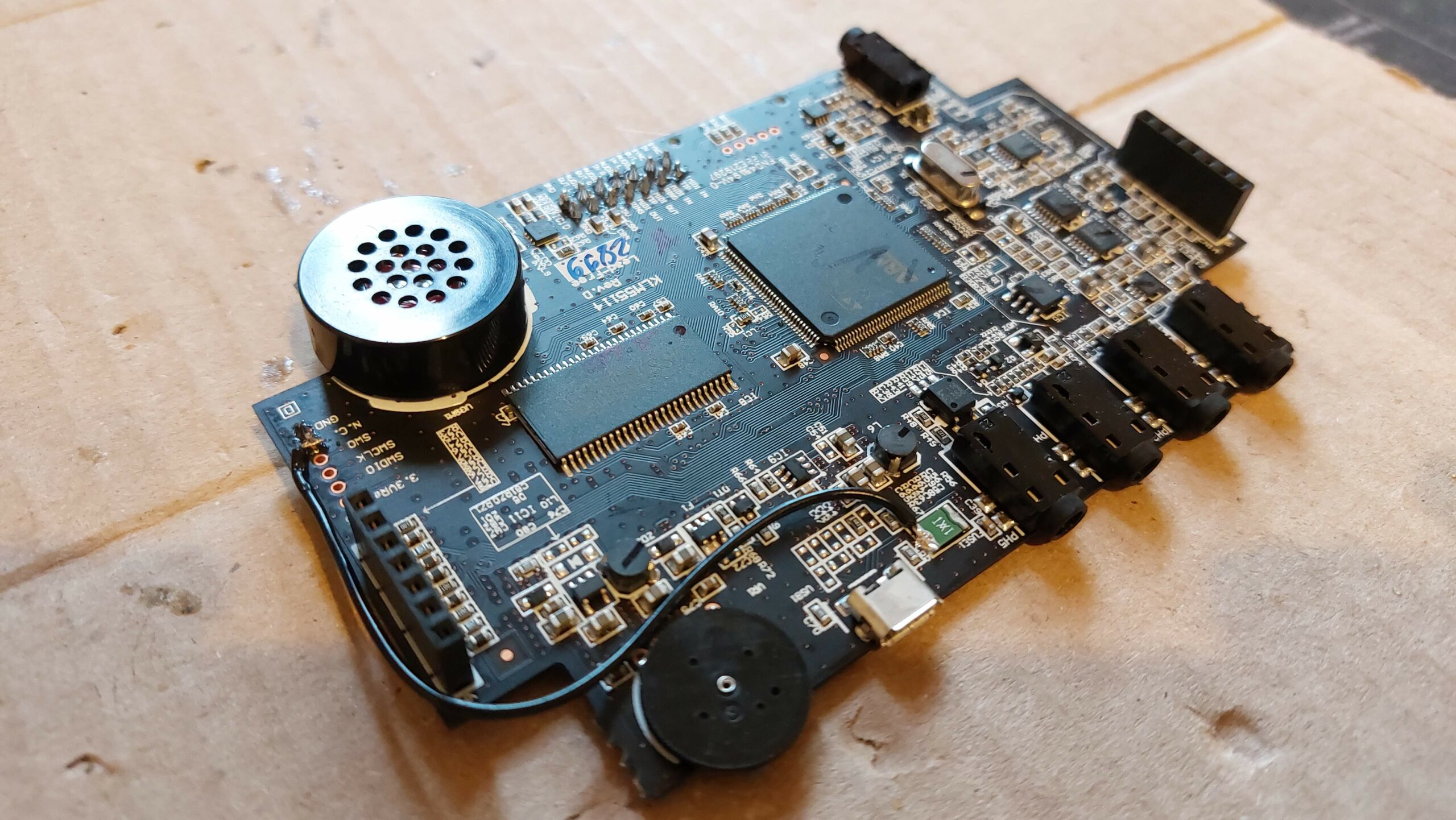
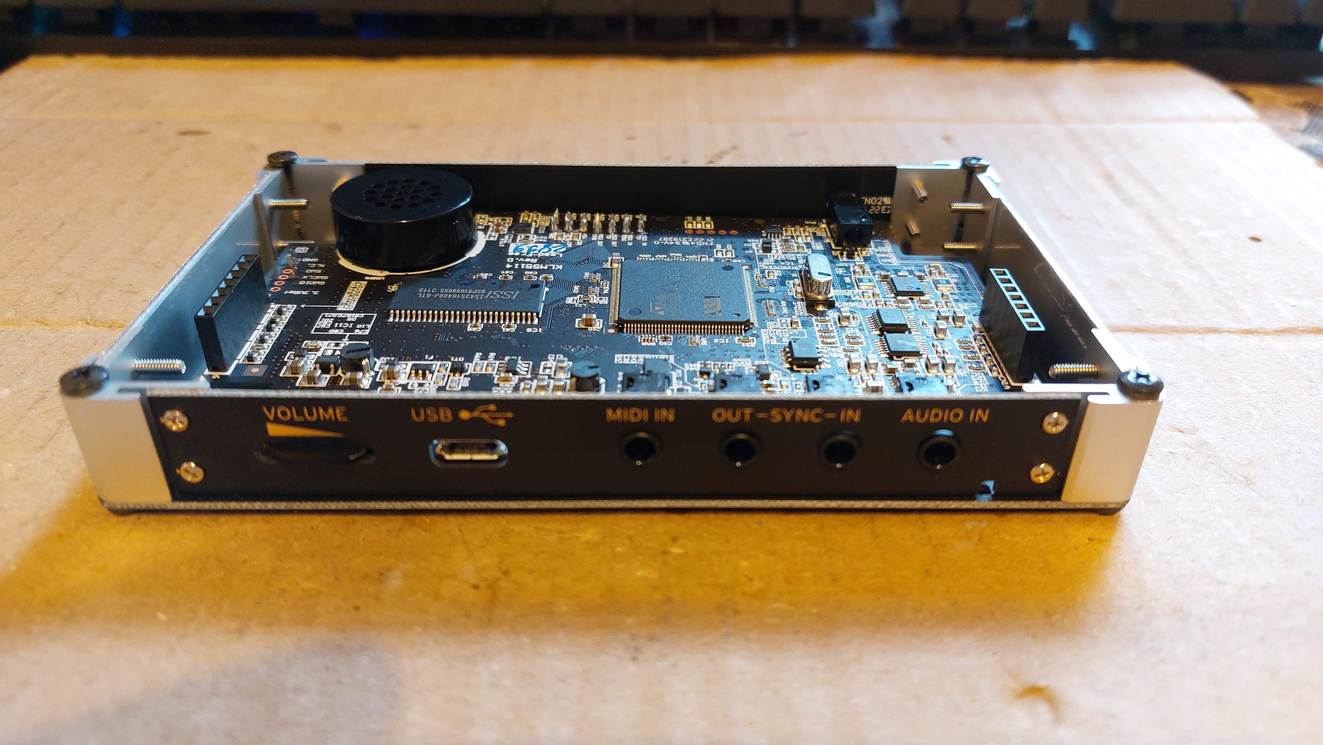
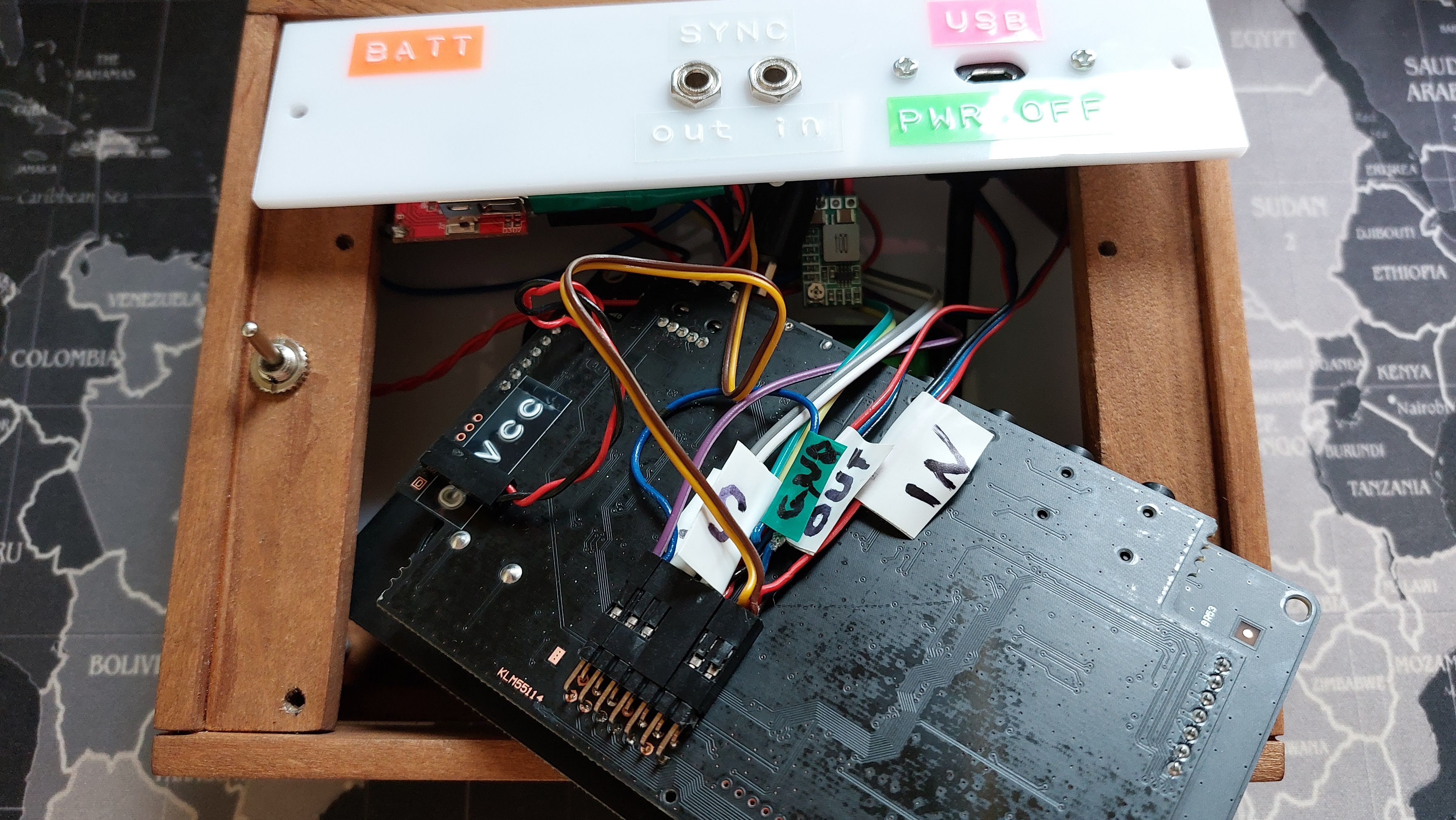
Notice that this pcb is newest revision (Rev.D) and it has breakout pins for every input and output socket. We will use that!
Solder angle pin connectors on the other side of the pcb.
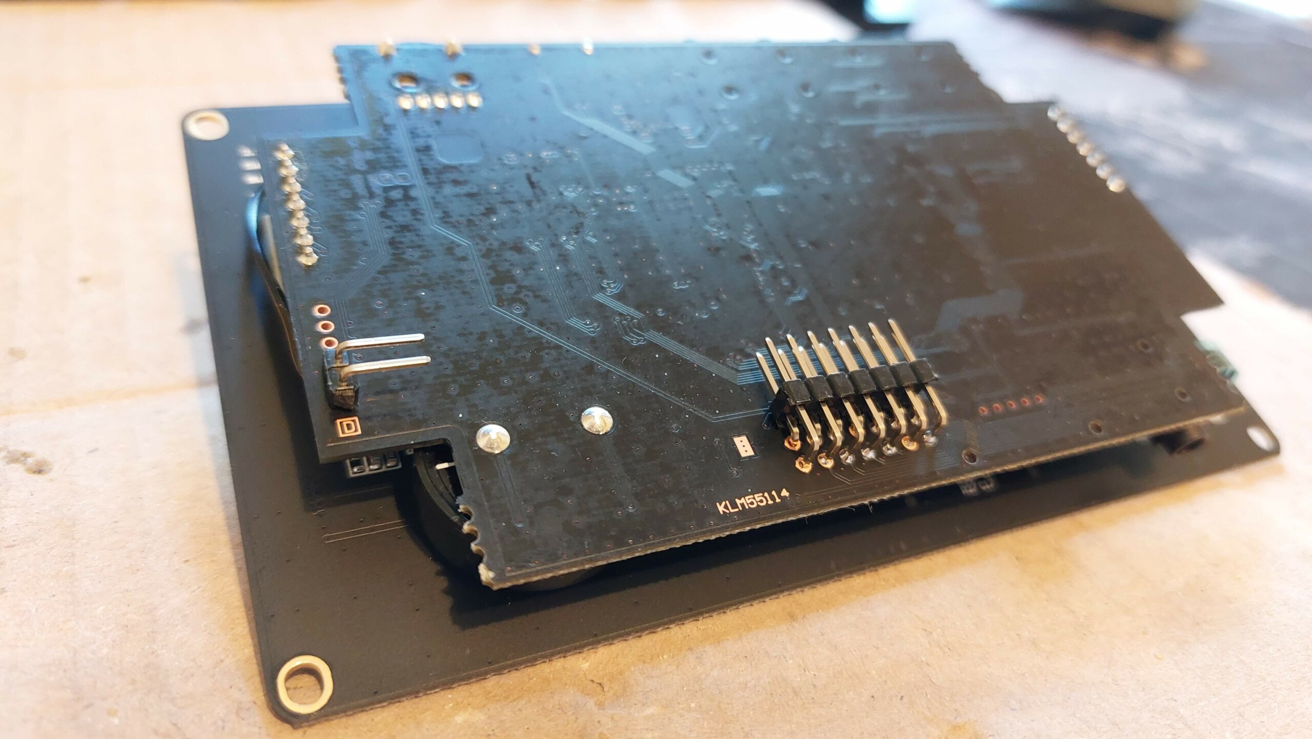
That way it can stil fit inside original case!
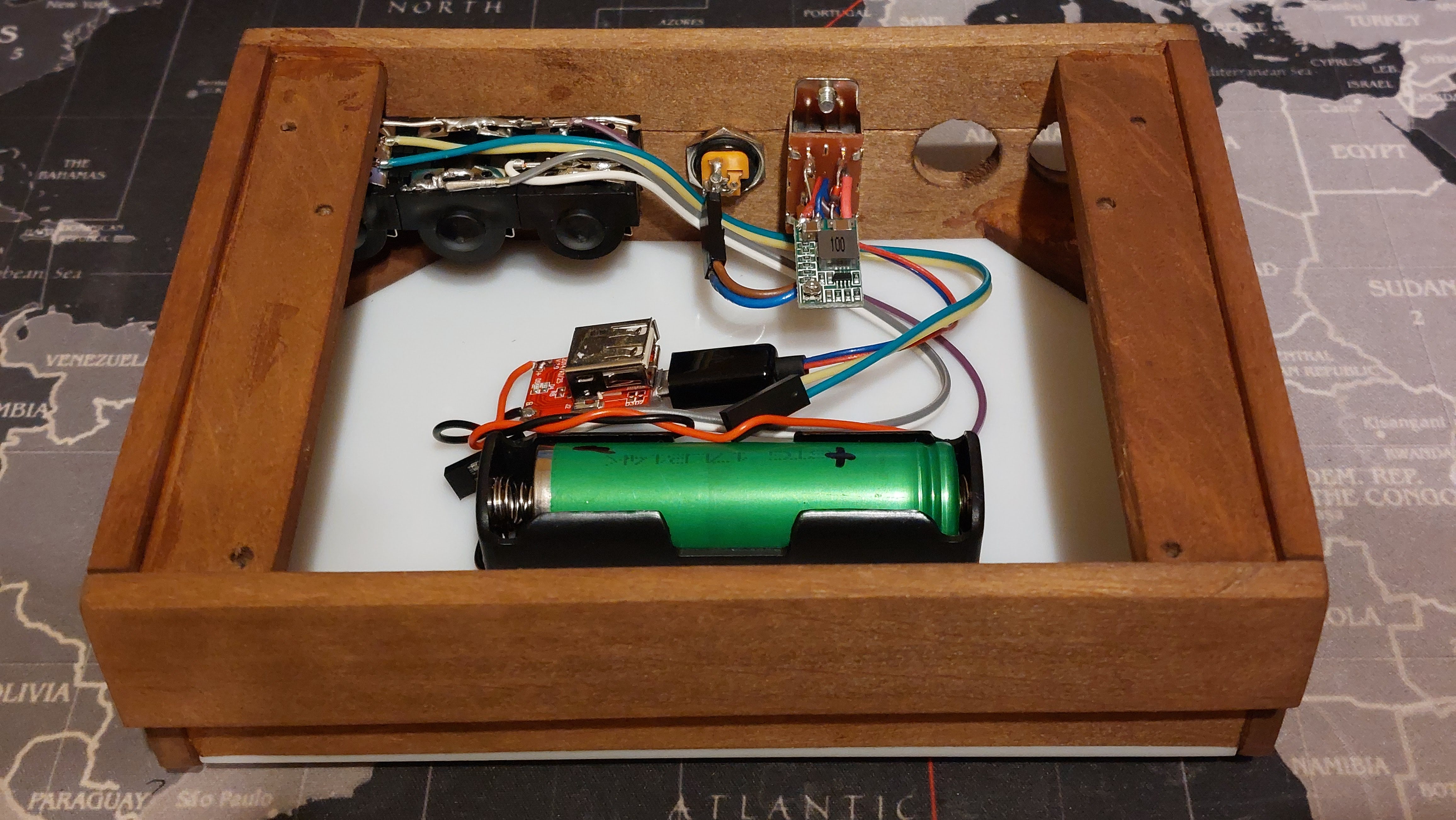
Testing our battery circuit. I’m using scavenged power bank Li-ion battery and pass thru charger. That way when you plug power on the back DC barrel, it will charge battery and power up synth at the same time.
Now we are redy to put everything inside the enclosure. Notice that the wood was stained. Hope you like the color 😀

Mount polarity switch and power IN DC barrel socket. Notice the socket can be disconnected.
5V output from the step-down converter goes to the micro USB plug that is connected to our battery charger.
Now mount rest of the sockets inside.
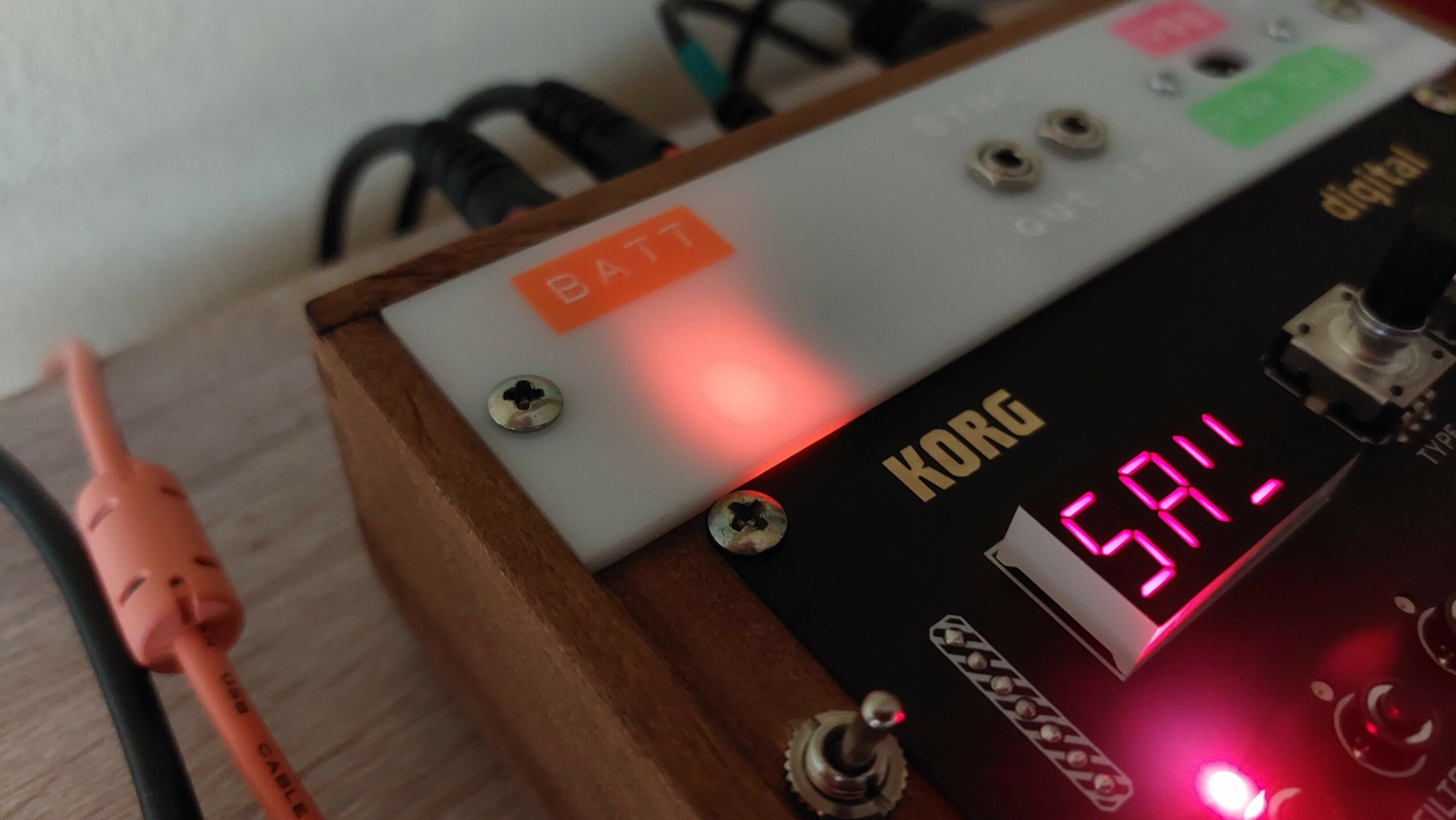
Now we can mount top panel. To be able to see what battery charger is doing, we need to glue down charger module to the panel using double sided tape. LED’s front to the panel. ABS panel will disperse light nicely.
Now we need to mount ON/OFF switch and the battery. Battery holder can be attached using M2 screw so we need to drill small hole on the center of the bottom ABS panel.
Now connect every socket according to the breakout pin labels. I also labeled my wires and panel sockets.
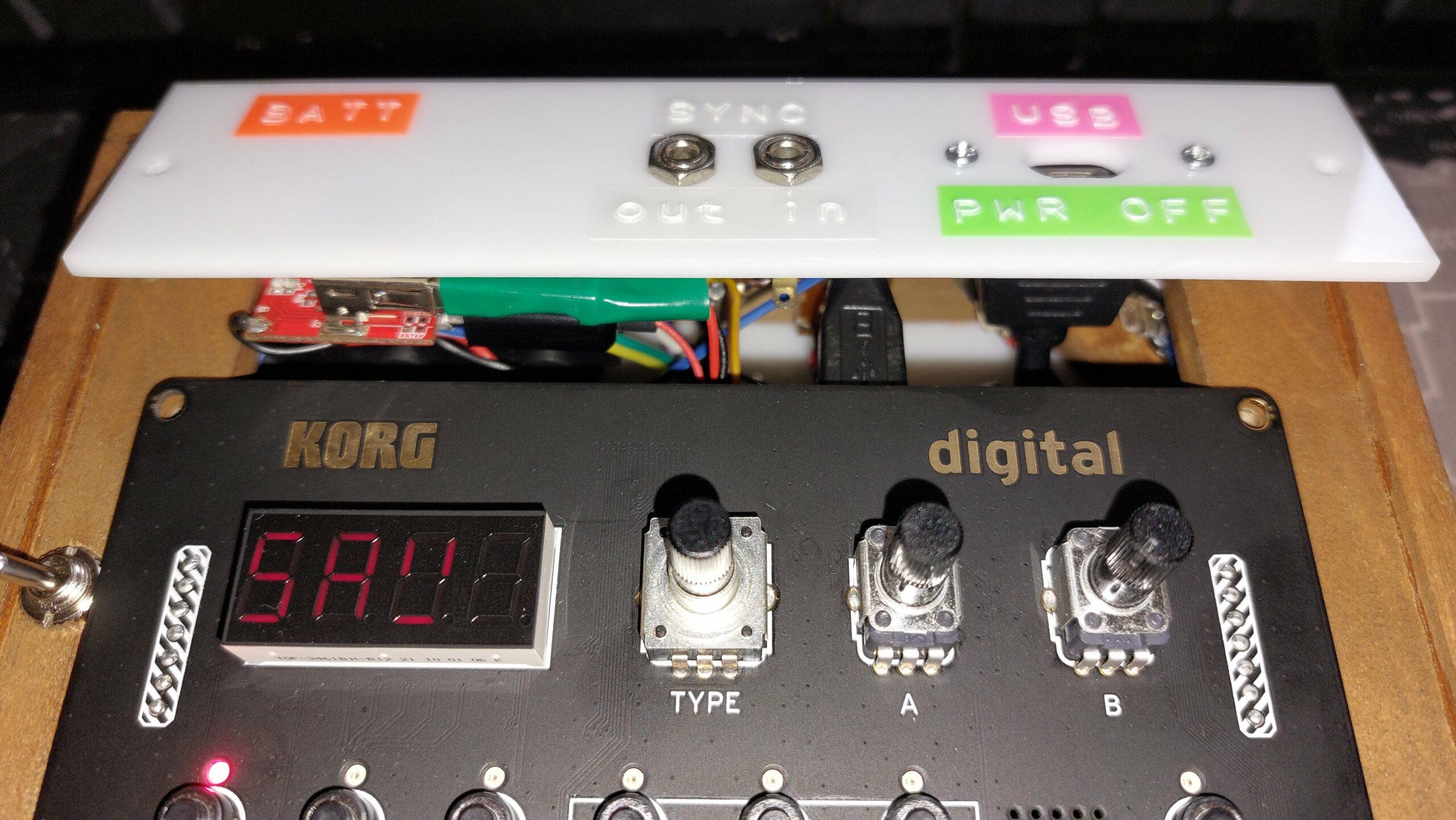
Now we can mount NTS-1 front pcb to the case. Don’t forget to connect extension USB socket!
Also remember to TURN OFF synth before connecting it to the computer, because it can blow the fuse on the synth or in your computer USB socket! That’s why it’s labelled USB PWR OFF!
Put some labels on the back.
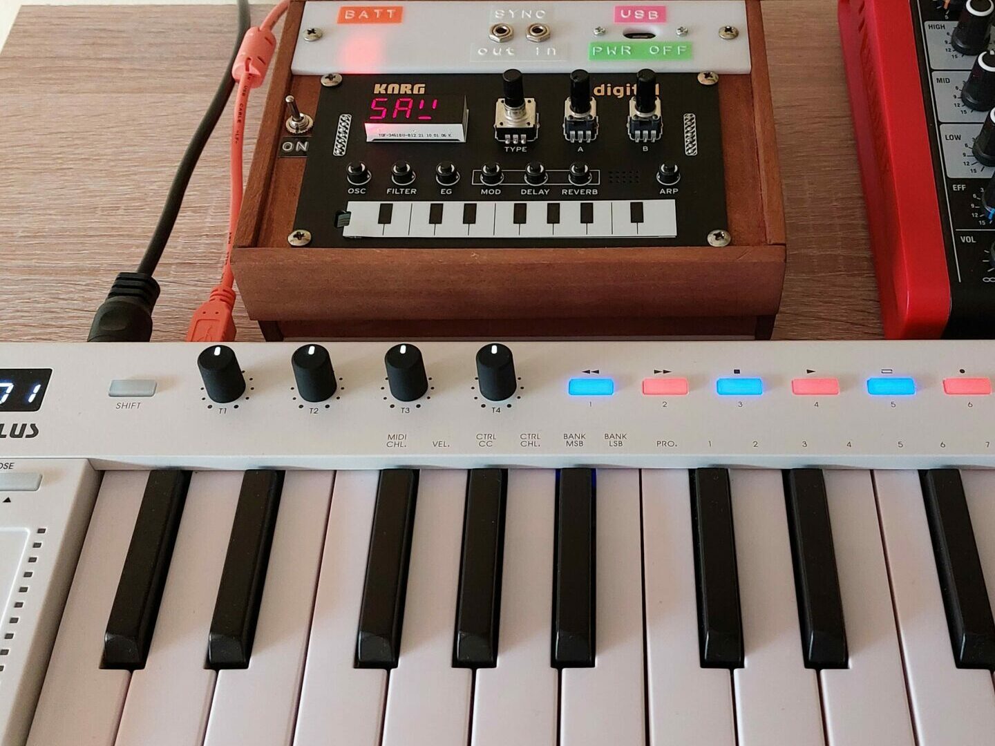
There you go! Finished Korg NTS-1 wooden custom case goodness!
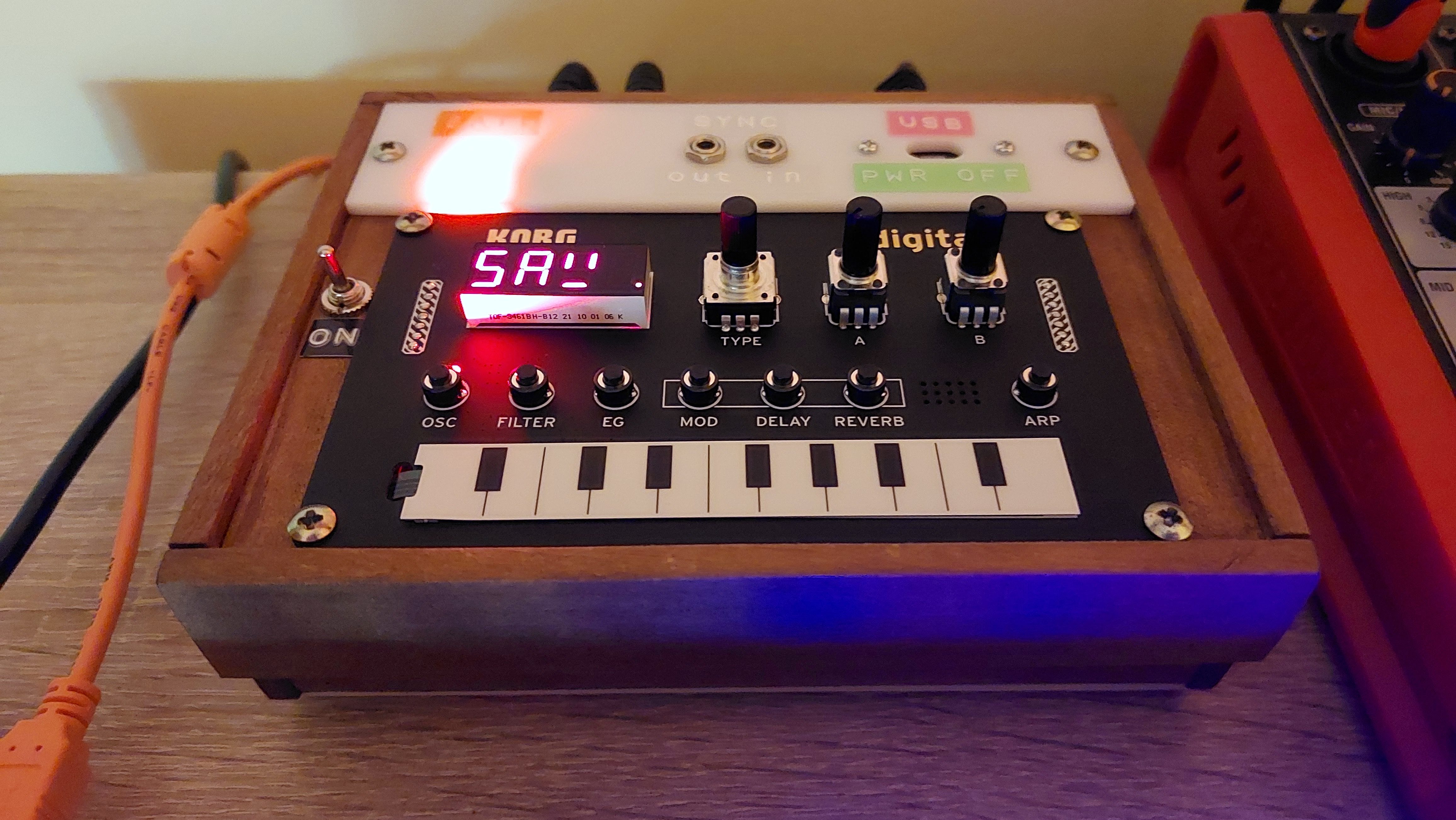
Connect all cables and test the synth. Red LED means battery is charging.
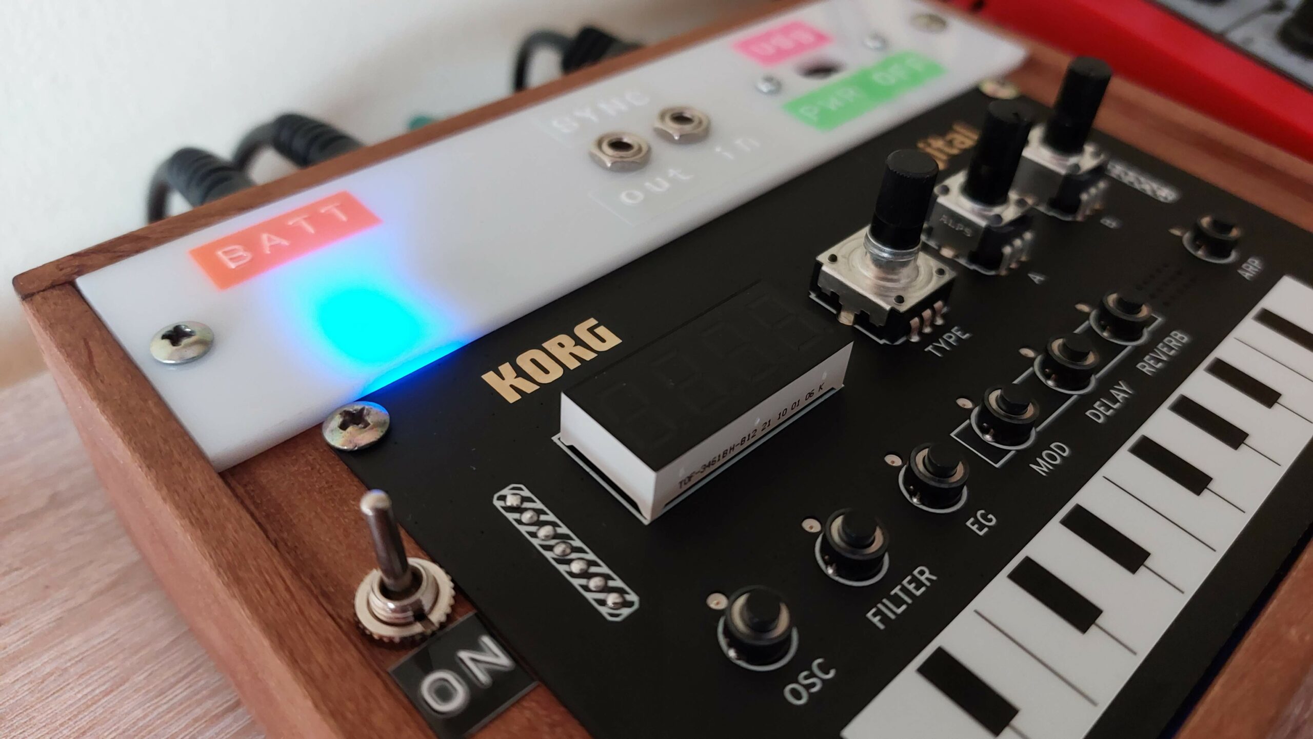
When battery is full, LED turns blue.
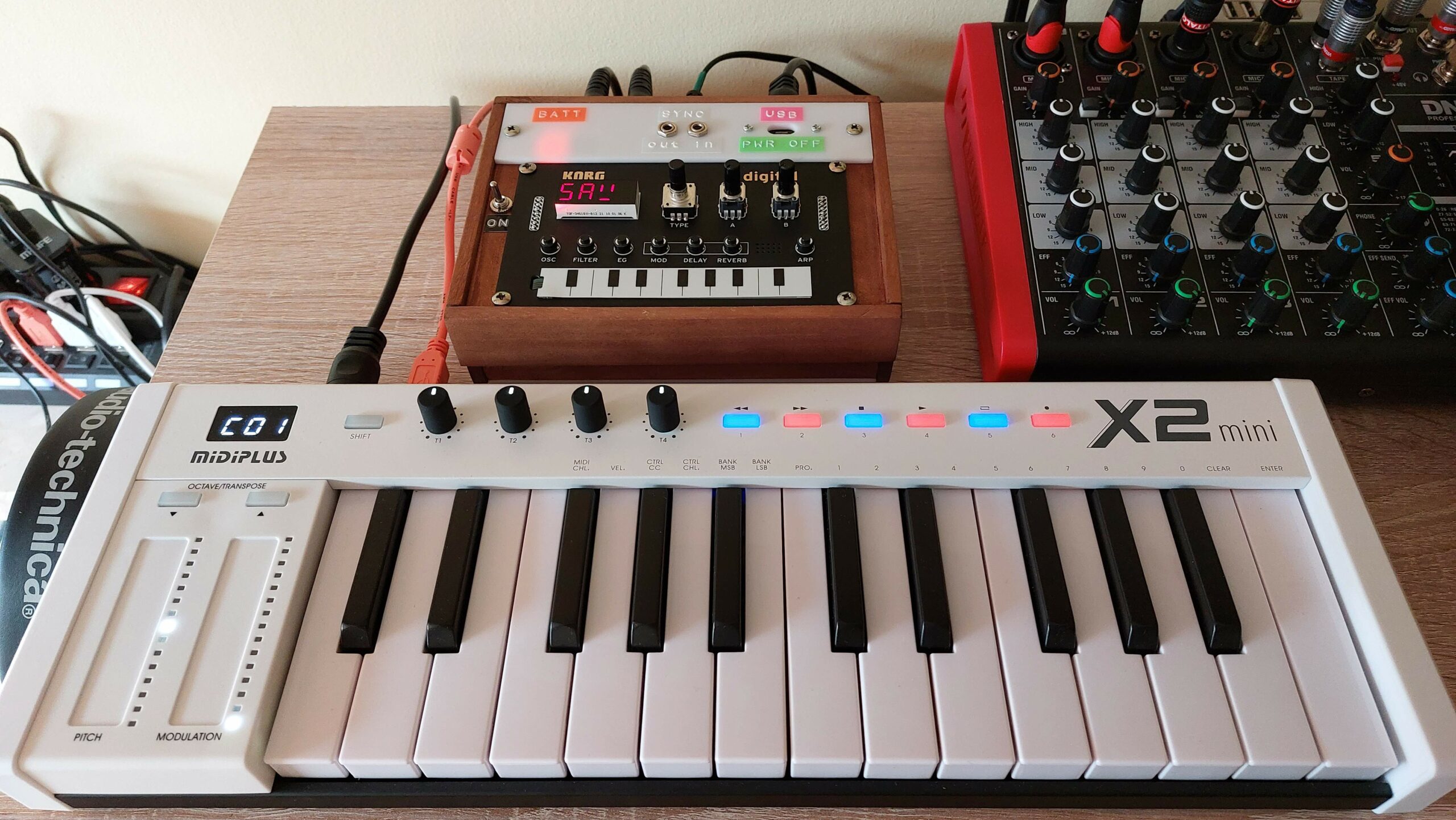
Now you can use it with Midi keyboards, sequencers, or as effect unit only.
If something is not working, don’t worry just switch wires on the breakout pins according to the pcb labels. Remember that audio jack slave is GND, ring is Right channel, tip is Left channel. Midi has only two wires so switch them around, one way or another must work 😀
Here are most important parts used in this build that I recommend using: