
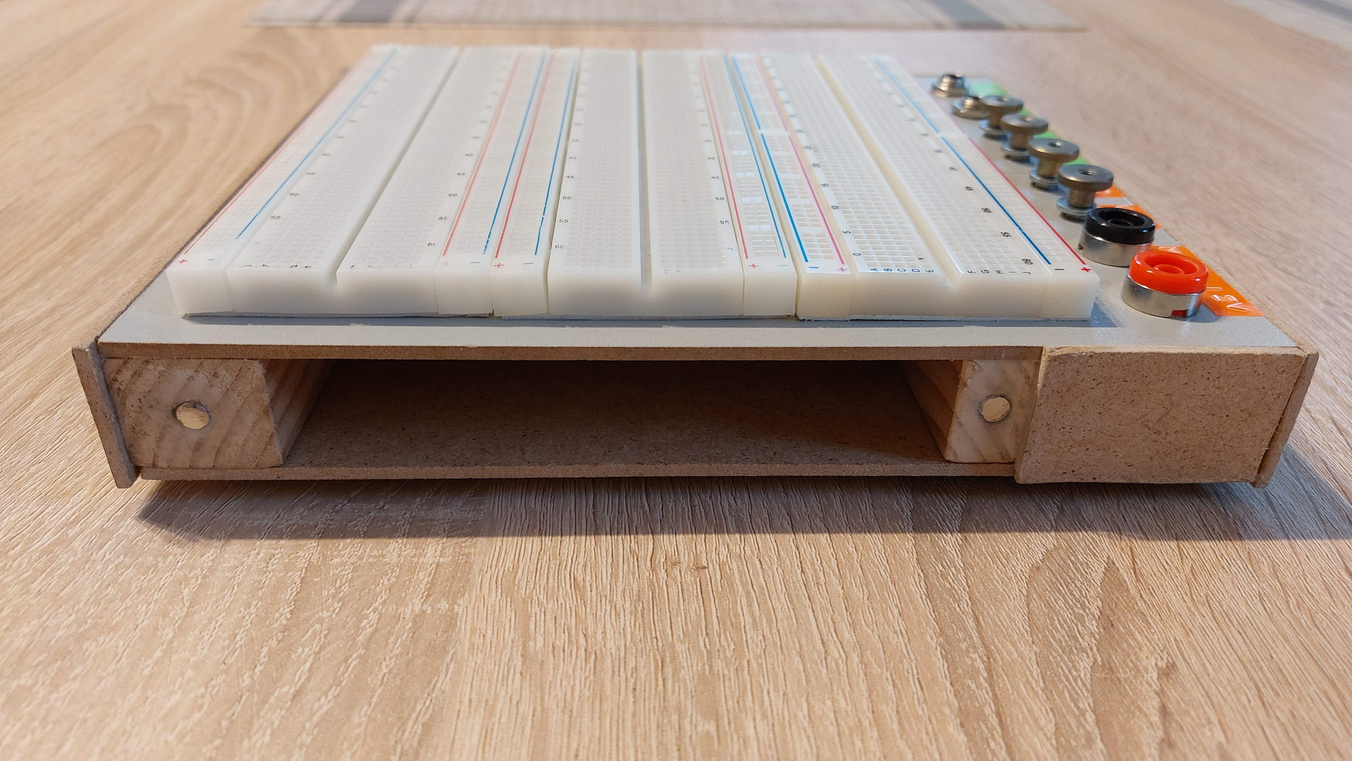
Another project that came out after cleaning my drawers from scraps, and stuff laying around. This time I have found couple of different brand of breadboards and I decided it will be good to use them as one unit by sticking them to something. I search the internet and noticed people are making awesome custom breadboard projects with build in stuff like LCD displays, knobs, switches. I always waned to have some of those breadboards with power terminals. Of course I could buy one, but I didn’t find what I need.

So I came up with idea I will build one after I found some pieces of scrap HDF’s (High Density Fiberboard) that was a piece of some furniture protective package. I also needed some device to test audio circuits with input and output sockets, some audio amplifier and speaker so I don’t have to attach so many wires and move all this stuff around which always end up disconnecting something from the breadboard.
Good idea let’s do it!
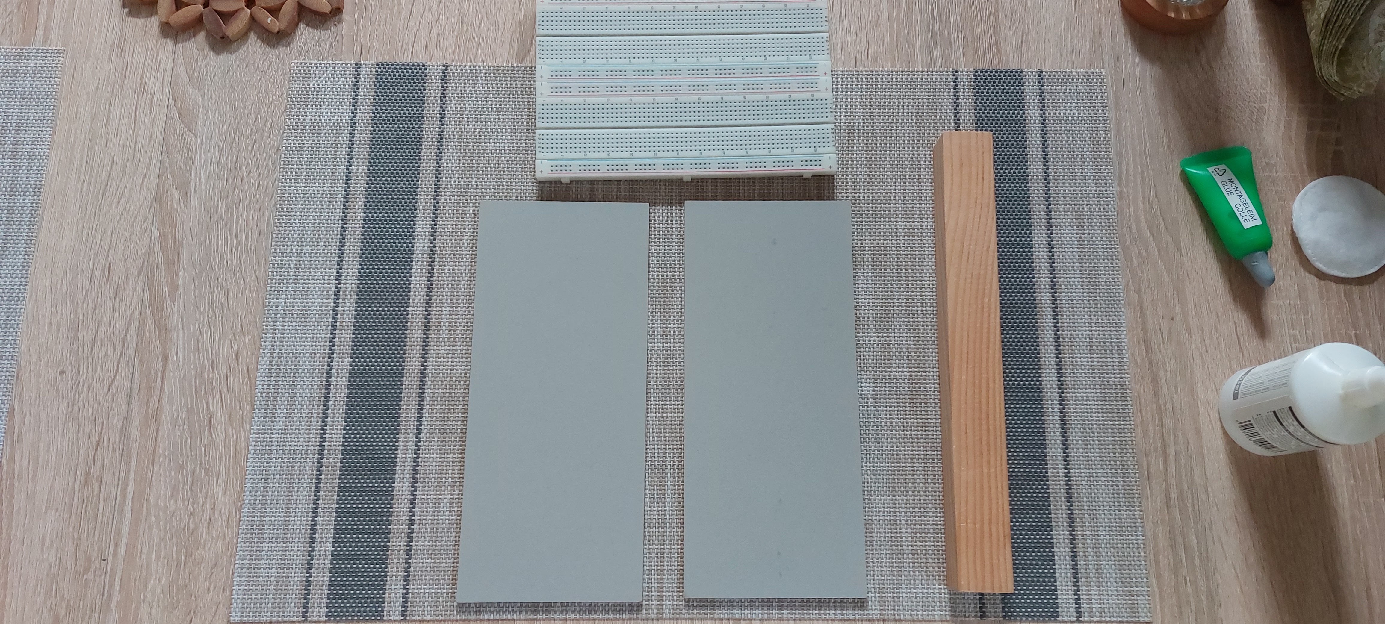
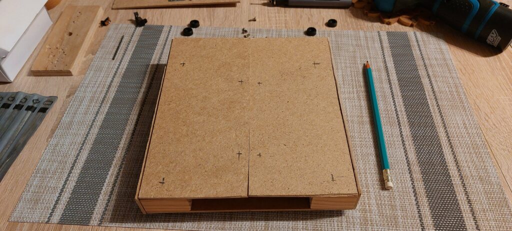
This is my scrap material, oh it’s already painted and it has perfect dimensions for three stacked up breadboards, how convenient! So we have front pieces but we need to join them somehow. Oh look there is some random piece of wood there, we will use it!
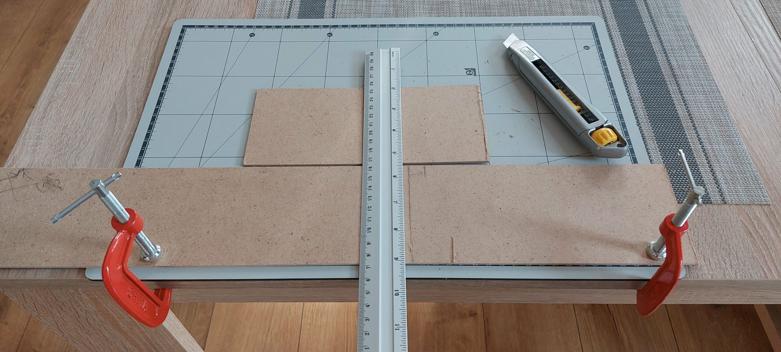
Now we need to do the same on the back but I don’t have nice pieces anymore, only big chunks left, let’s cut it up! Since those HDF’s are pretty much cardboard glued with some saw dust, we can cut it up with just a knife.
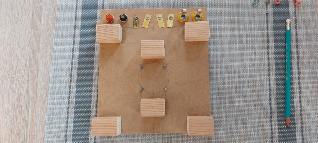
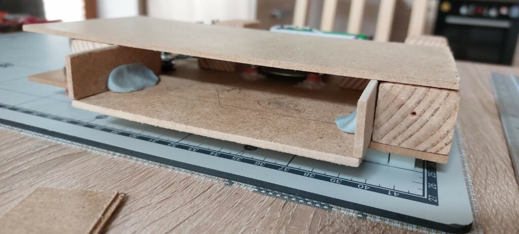
So we have all the pieces let’s join them together with the long piece of wood cut to 6 pieces that will create our inner support structure. I also drilled holes for our power and audio terminals.
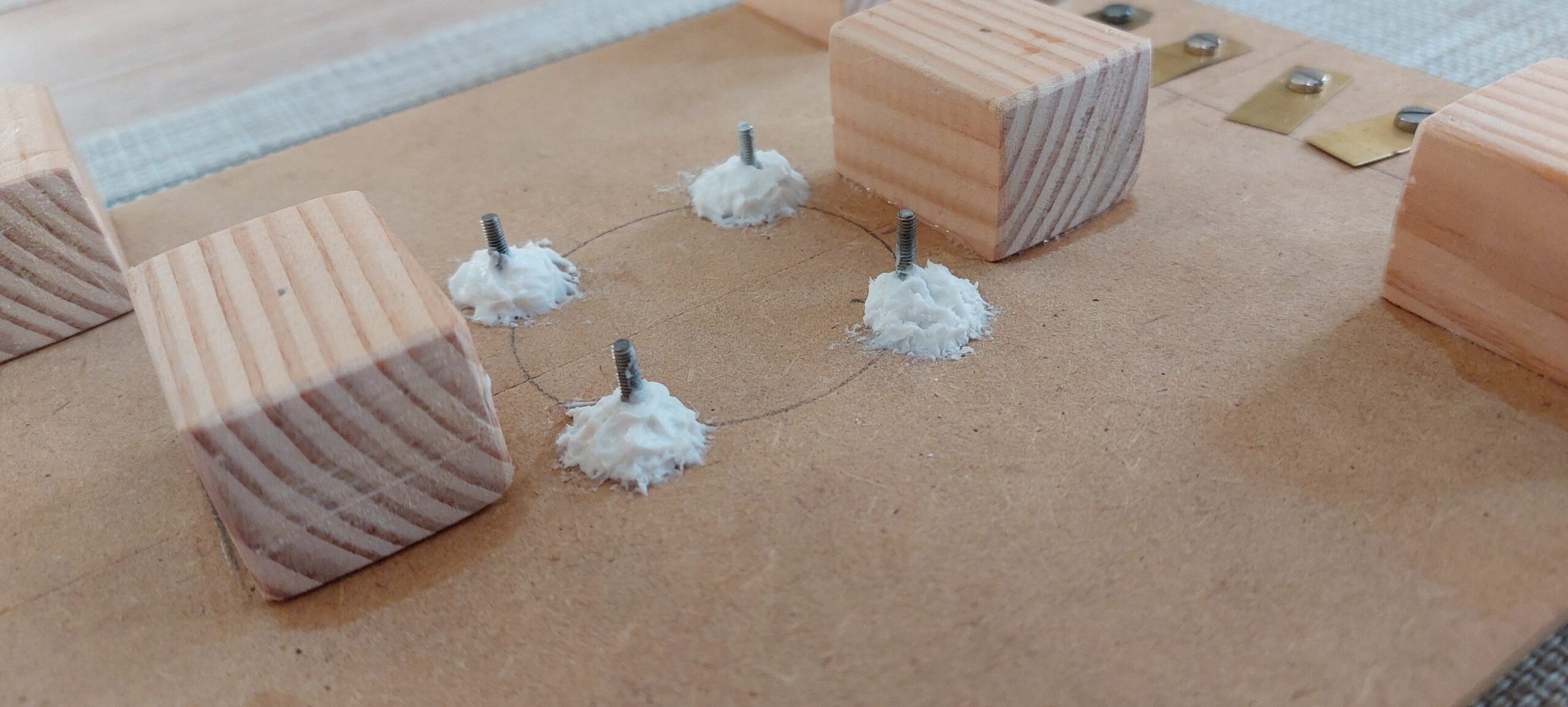
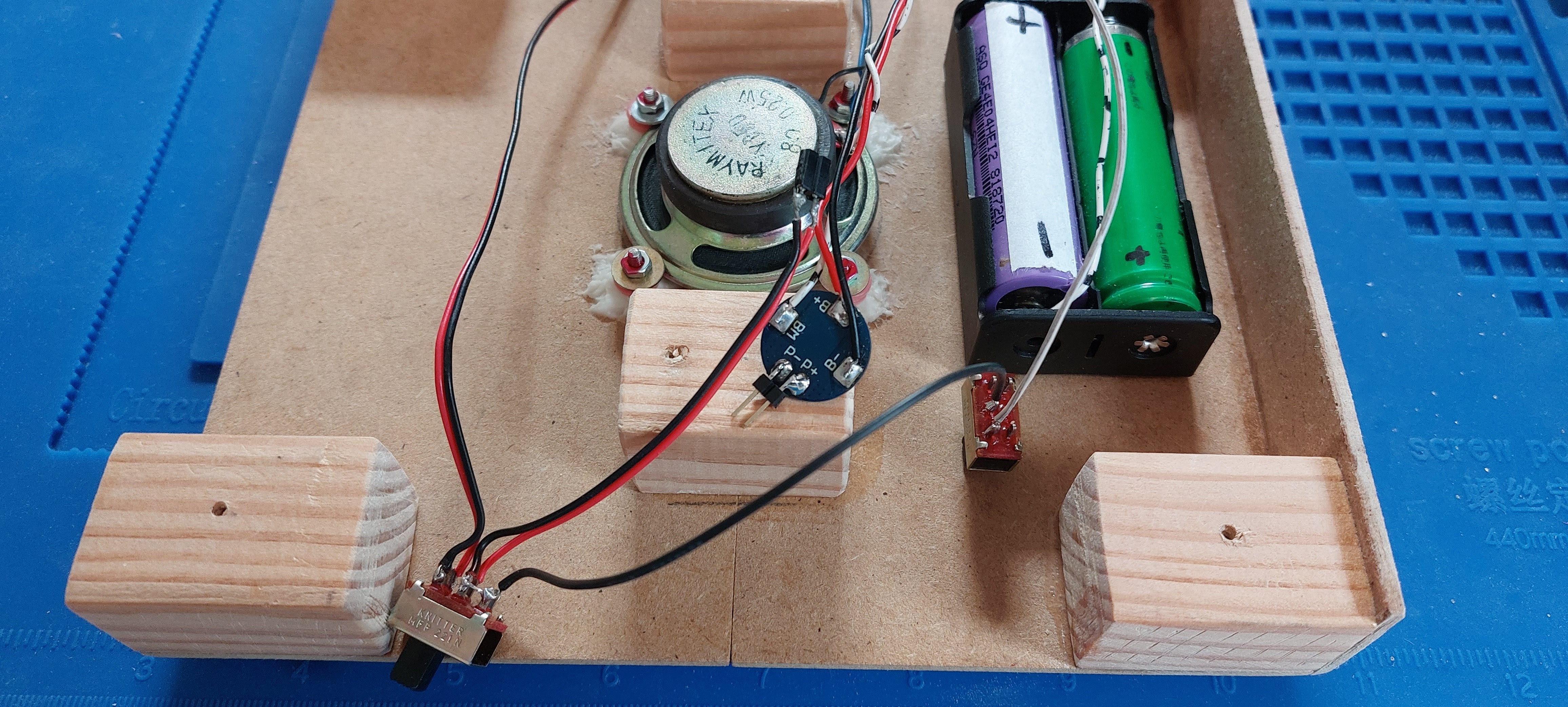
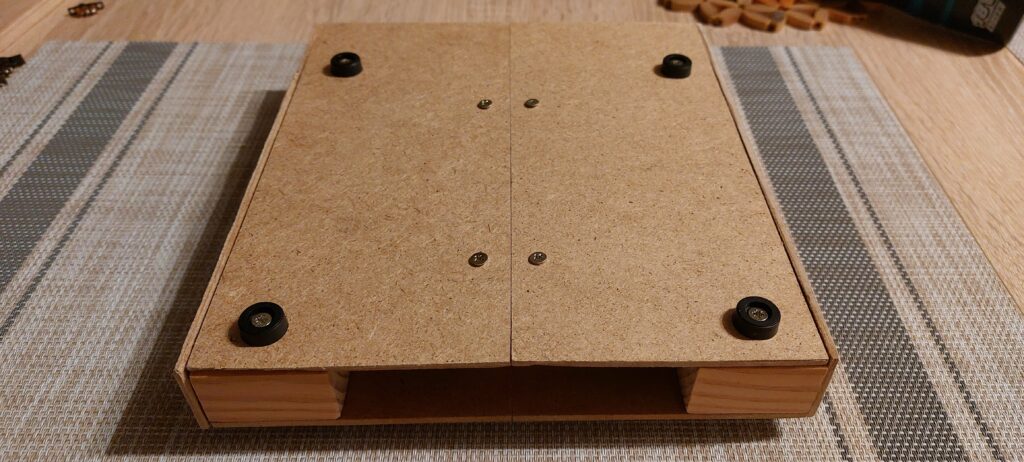
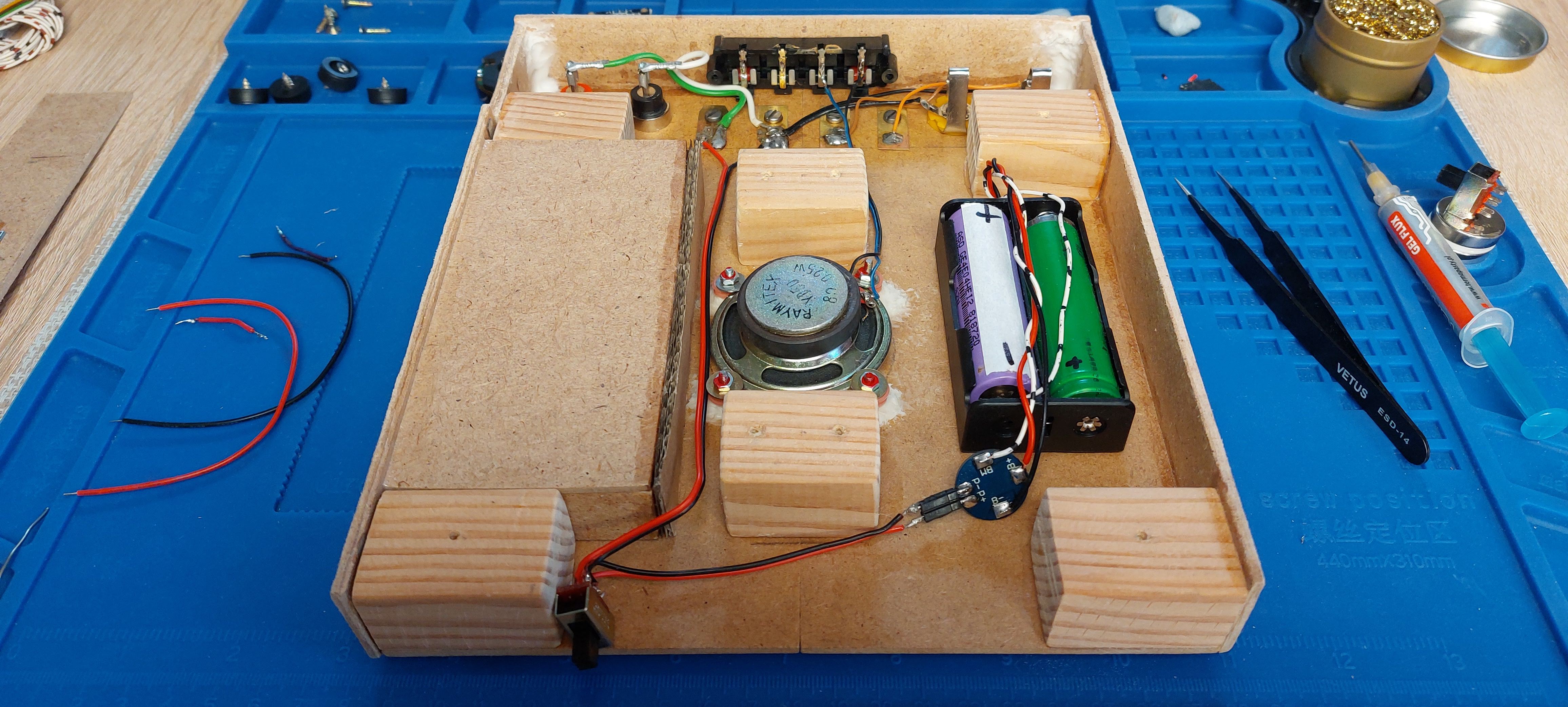
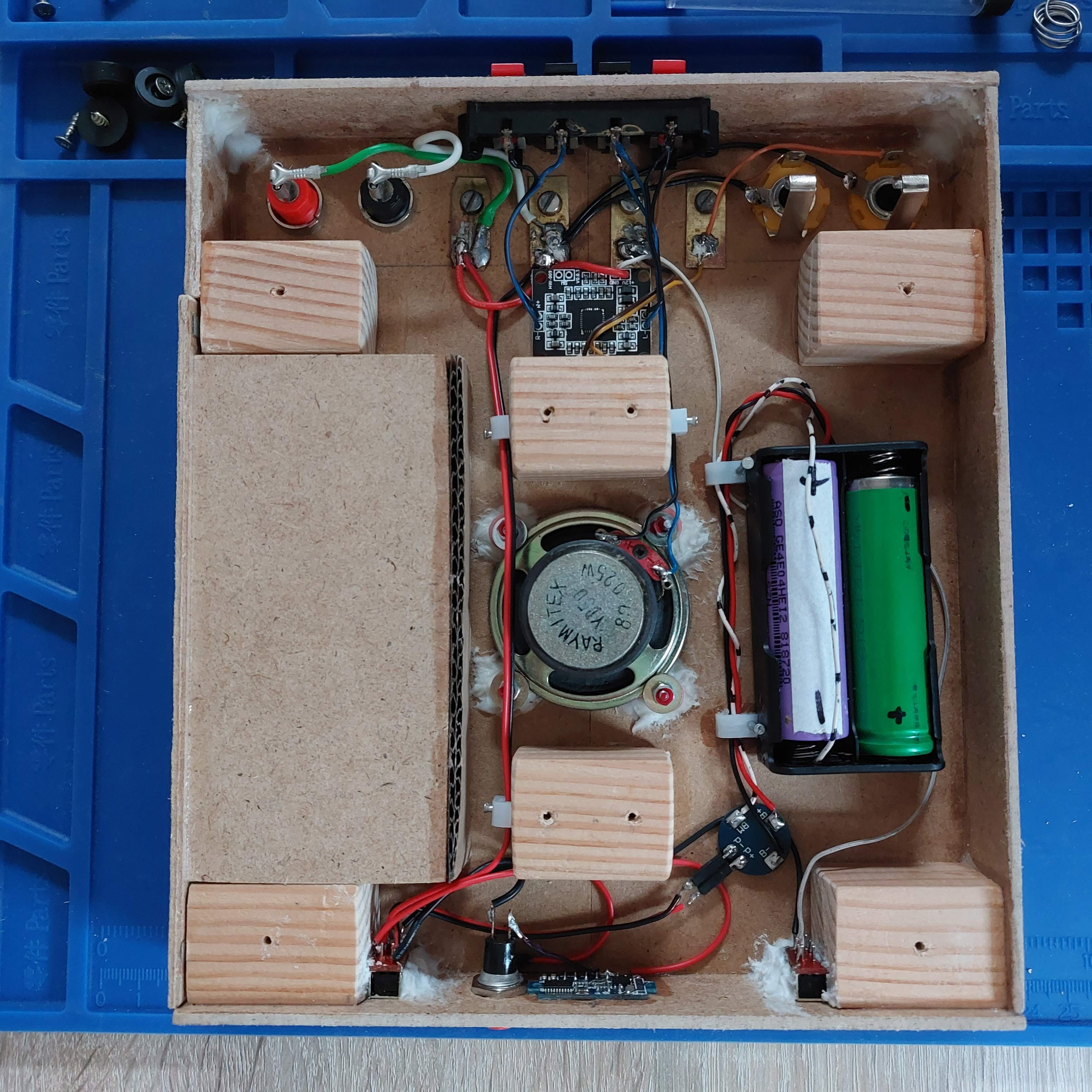
On the center we are going to attach the small 8ohm speaker, glue some screws to the board with metal wood glue.
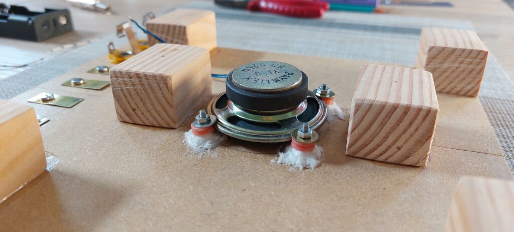
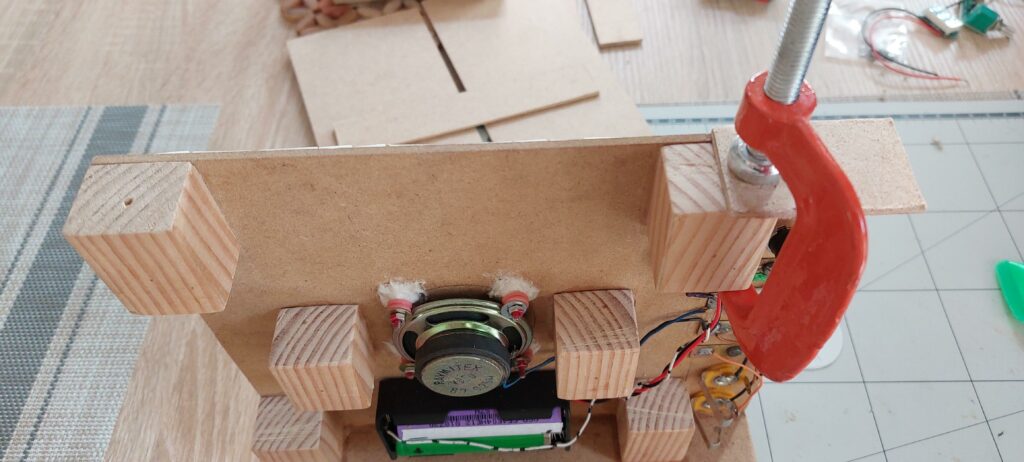
Speaker will be held by nuts and some washers, I also used some rubber gaskets to minimalize vibrations. You should also add on the bolts some sort of nut glue like loctite.
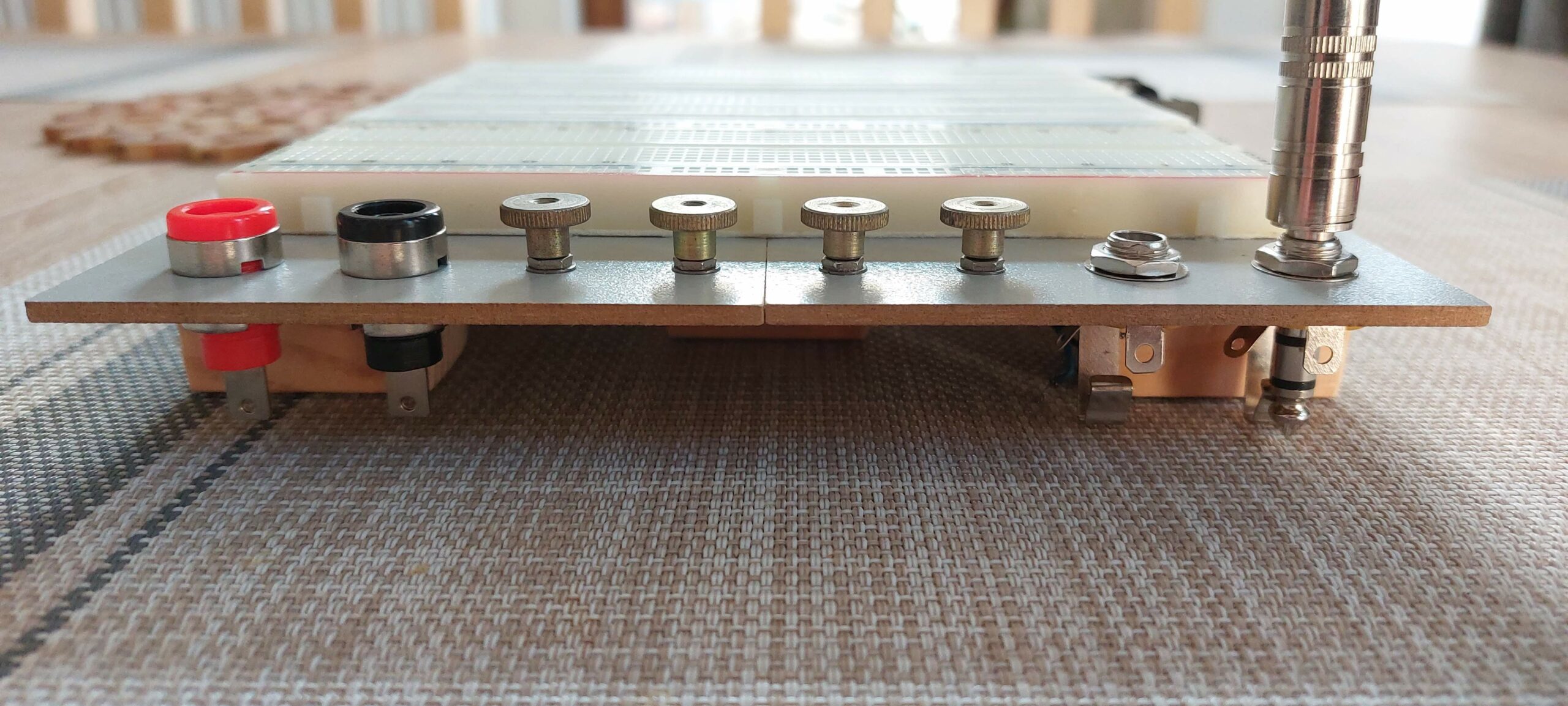
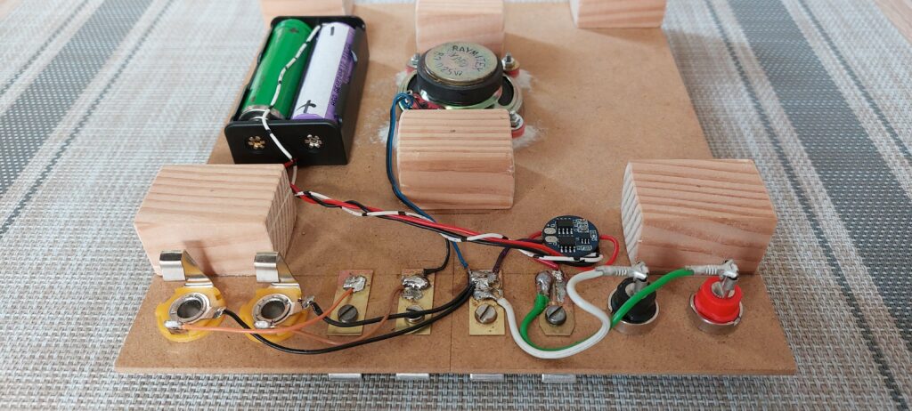
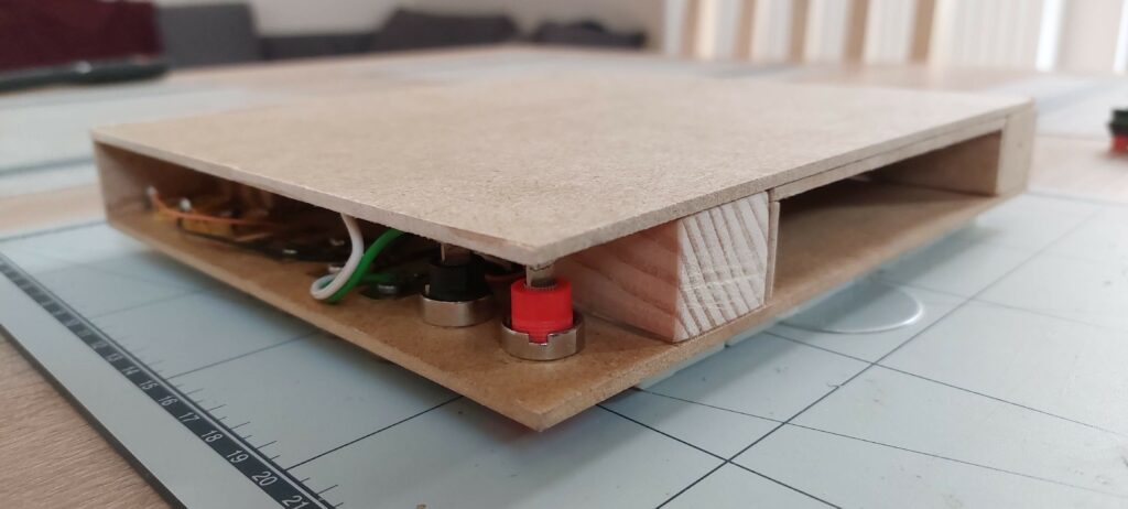
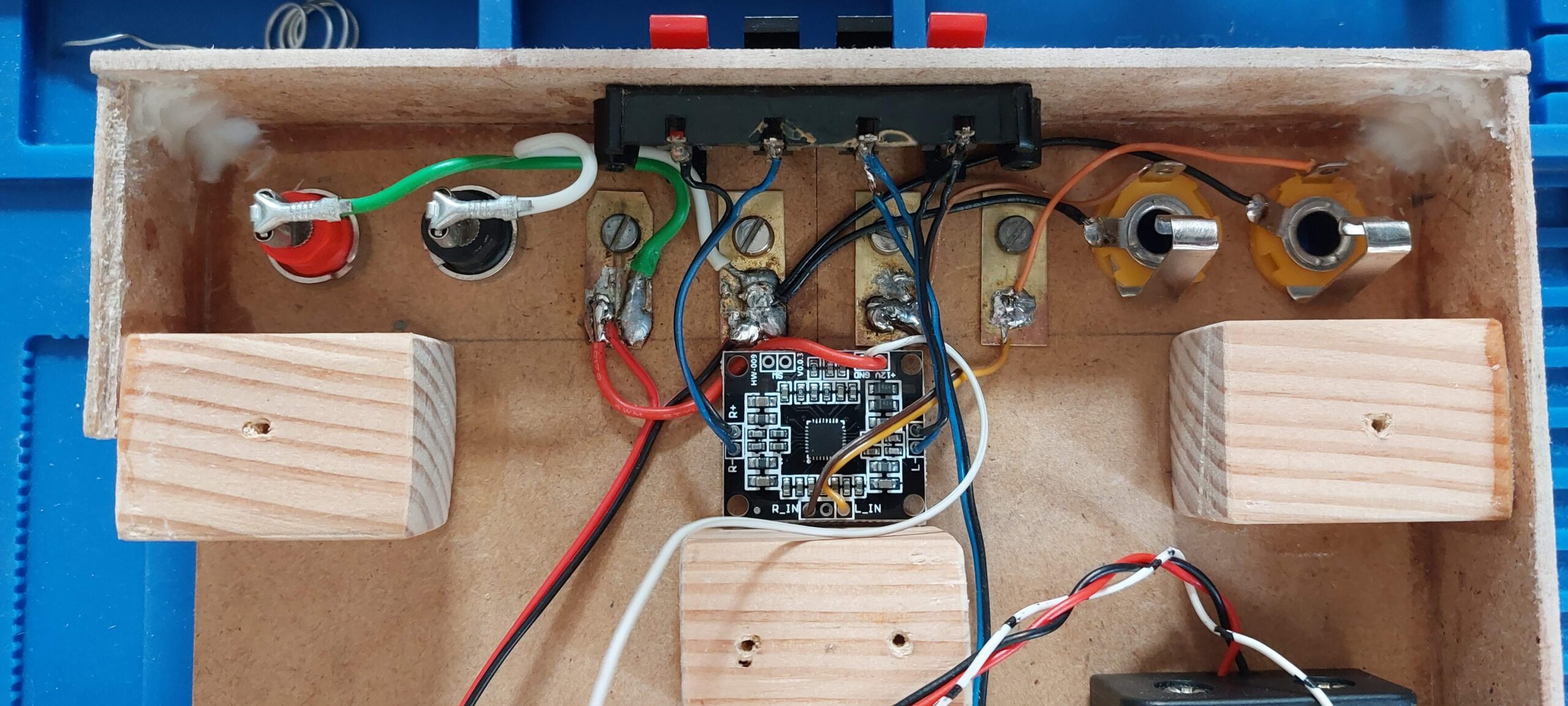
Our terminals are from the left, banana power inputs from the power supply. In the center those are old battery box screw terminals that I had from some railroad toys. We will use them as outputs because the are perfect to attach some pin wires to the breadboard. On the right we have 6.3mm audio jacks that can be used as inputs or outputs.
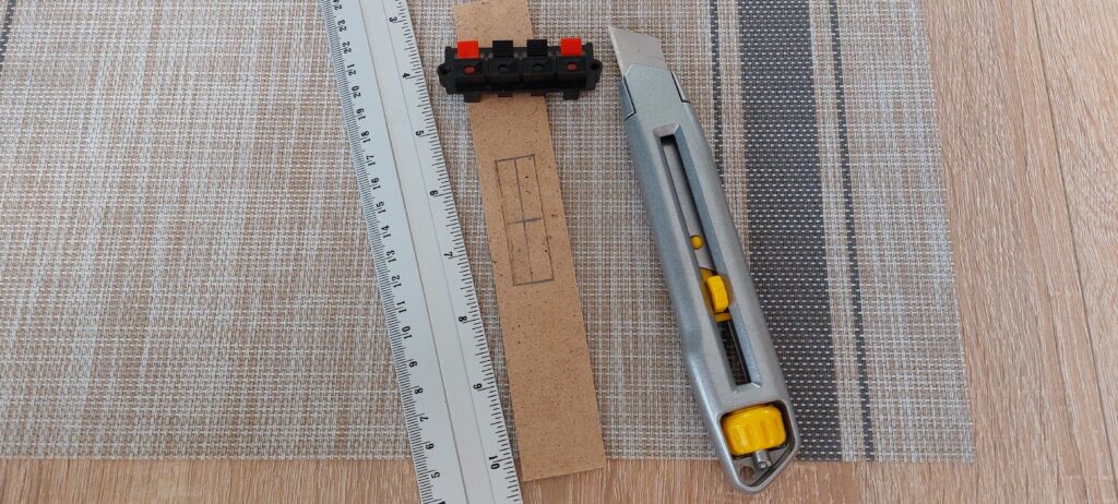
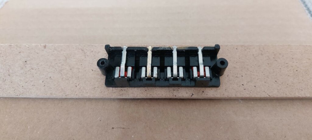
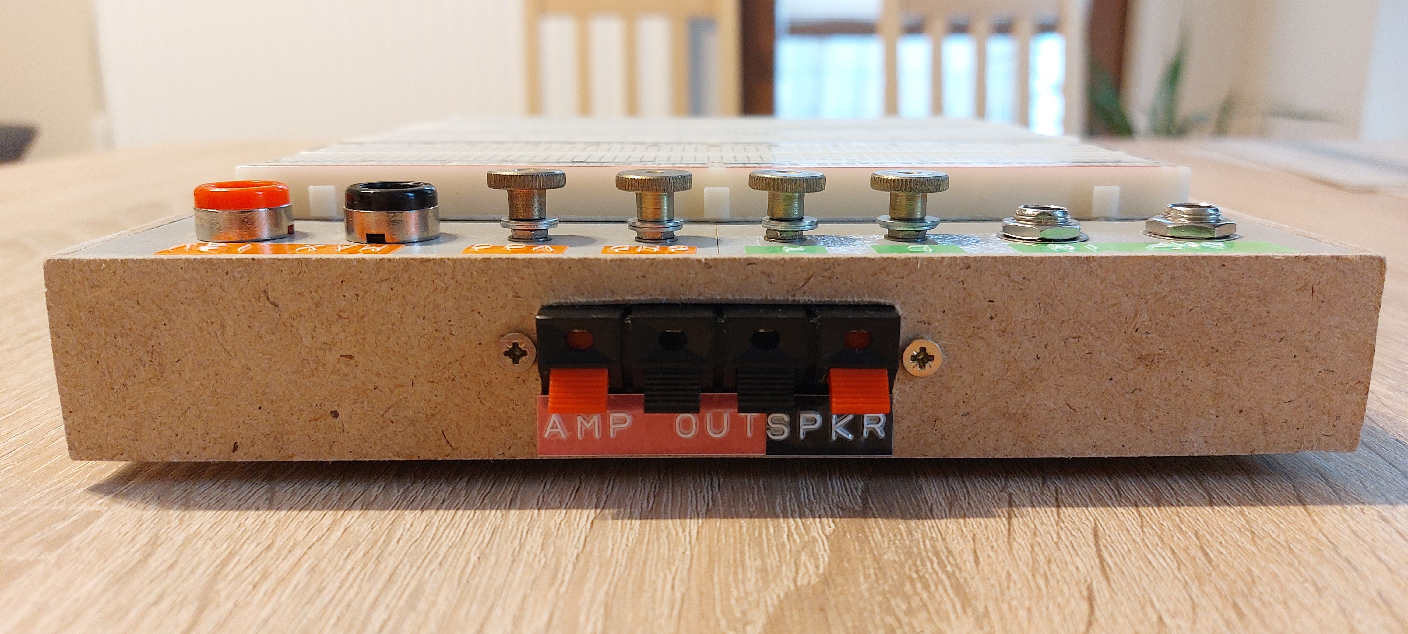
We also need some outputs from our audio amp and input for our built-in speaker. I had this scavenged speaker push in terminals laying around, we are gonna use it and attach it on the side panel.
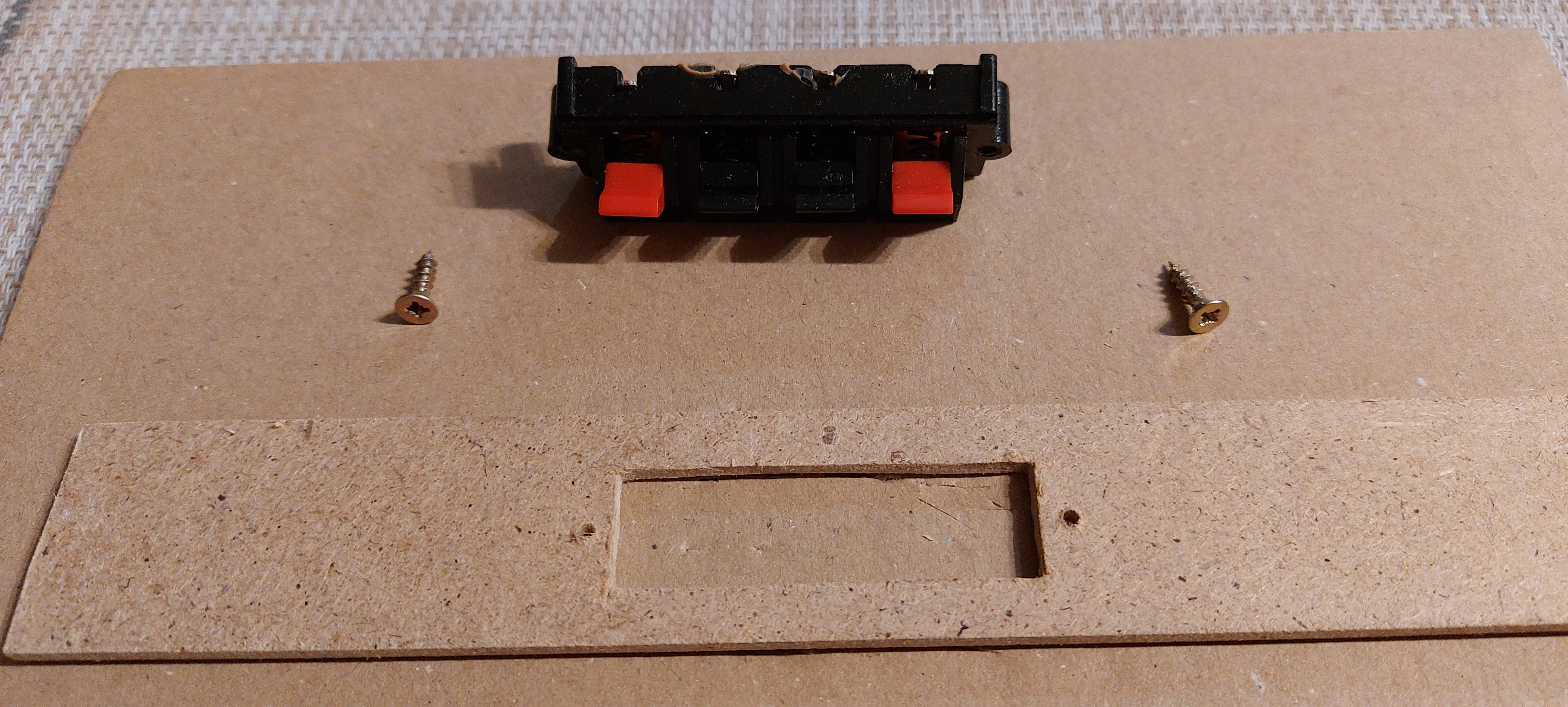
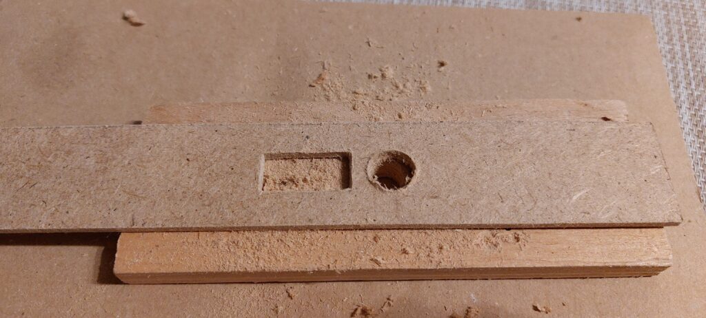
Cut some hole for it and screws to secure terminals.
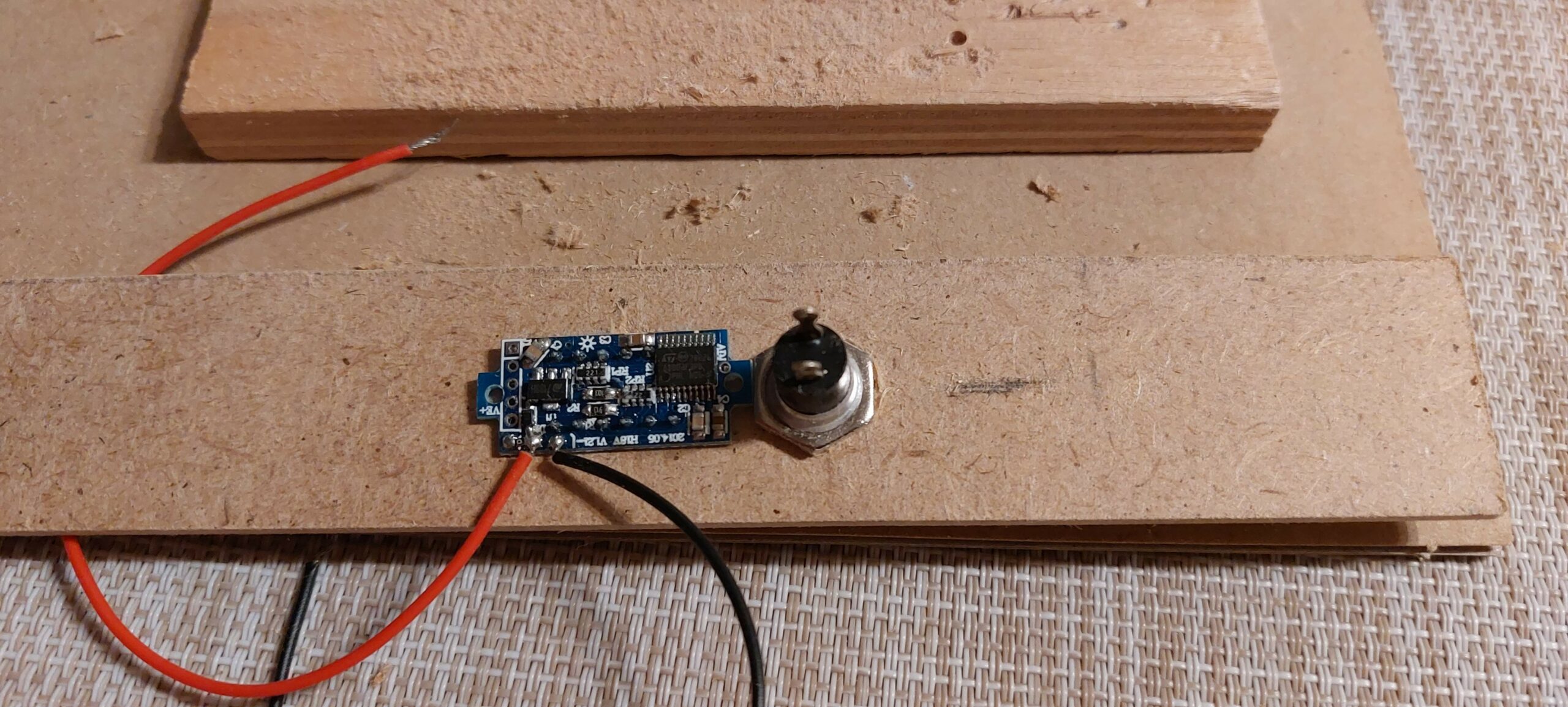
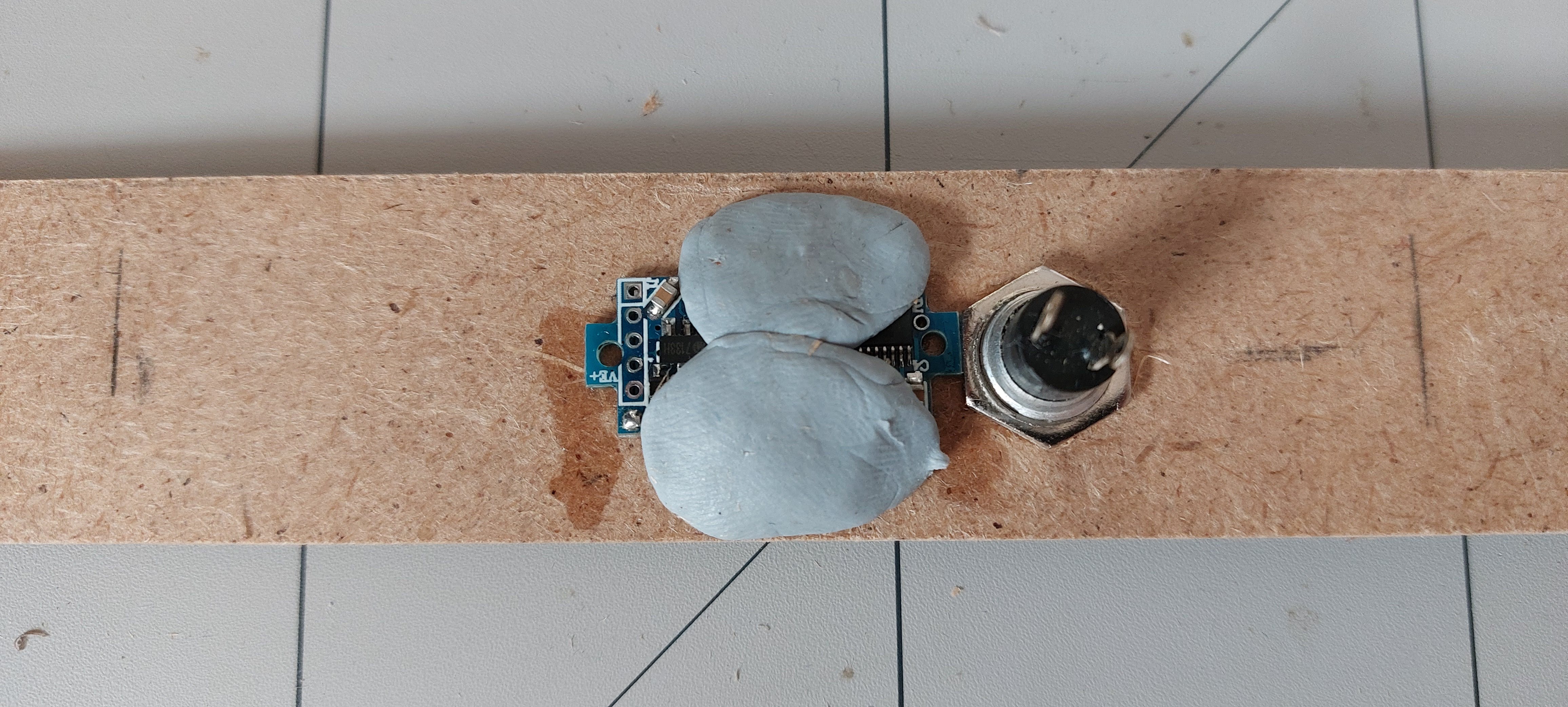
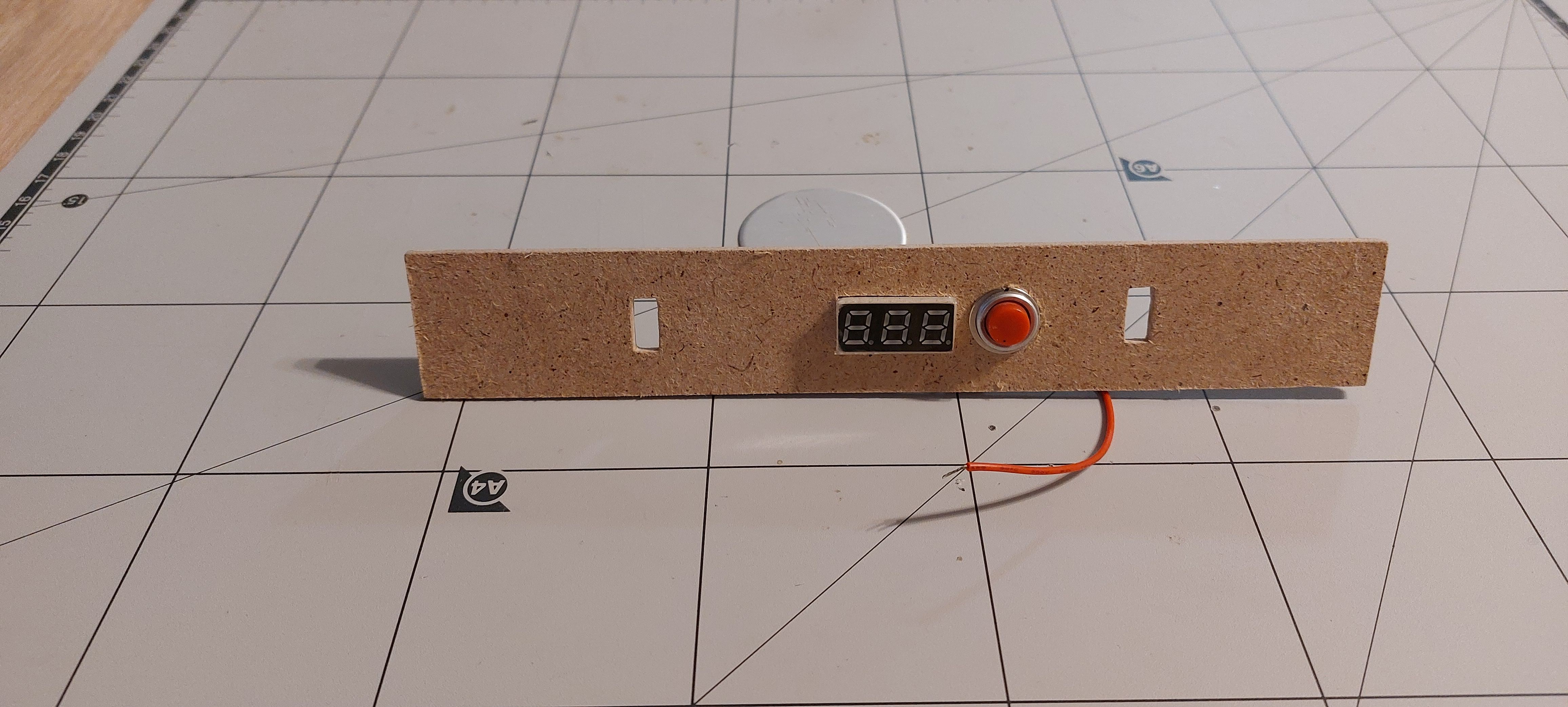
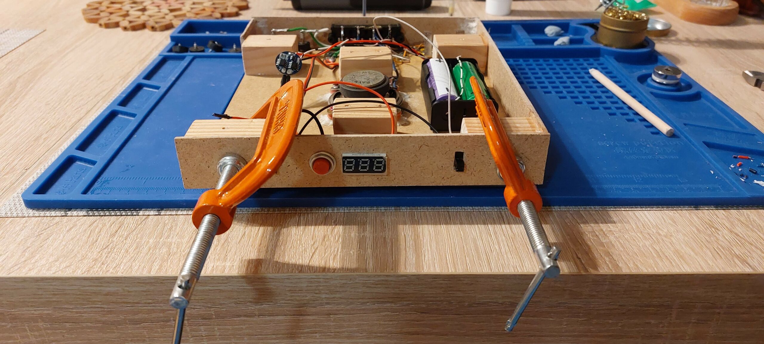
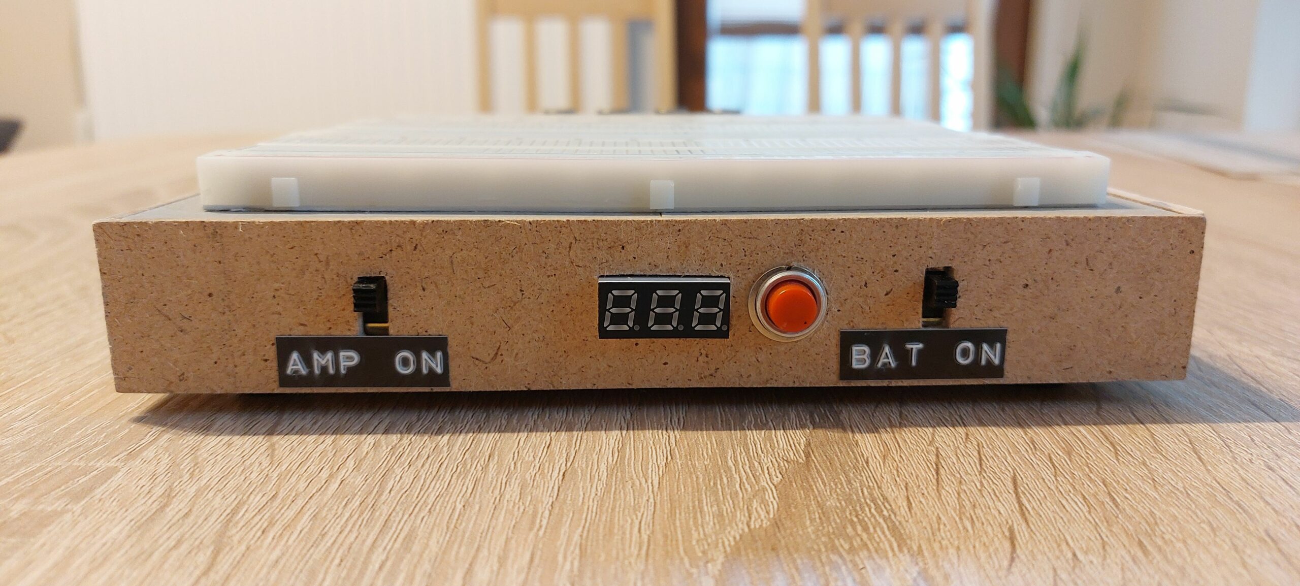
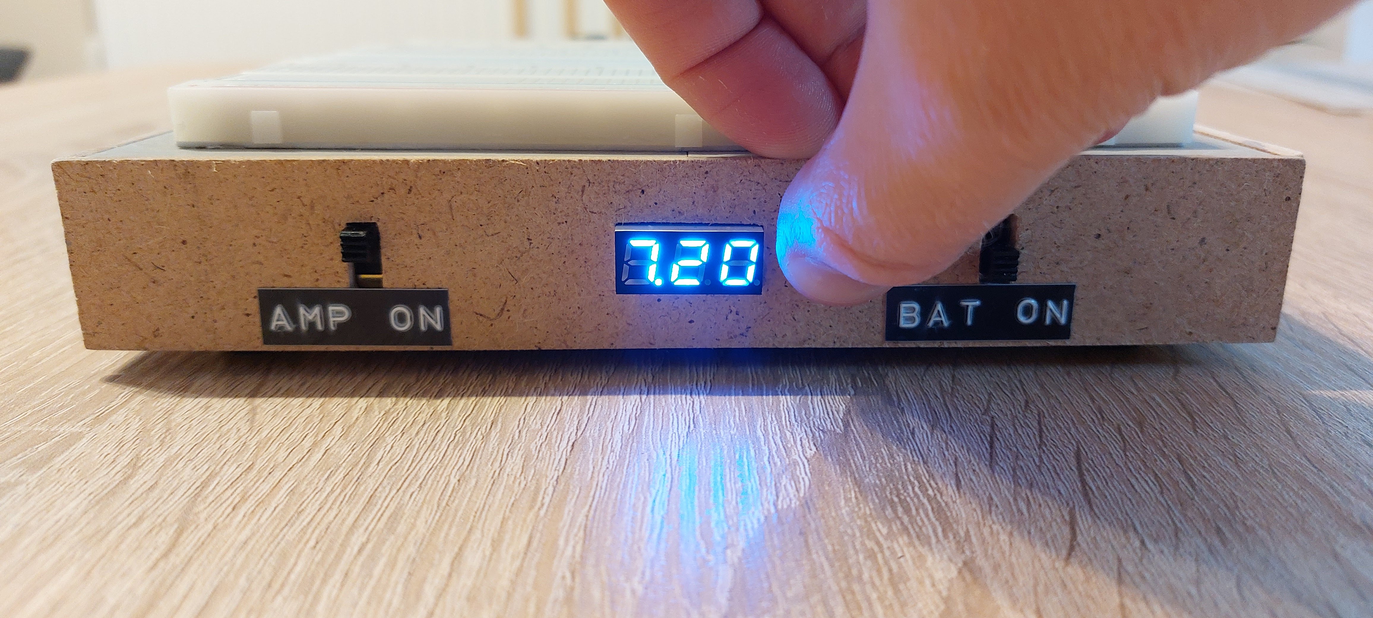
Now on the other side of we are going to place our Voltmeter that will activate with a push button.
Again drill some holes for Voltmeter and push button.
I didn’t want to drill too much holes to attach the Voltmeter so I just superglue it 🙂
Now cut another two holes for the amp and battery switches on the same panel as Voltmeter, this panel going to be on the front side for easy access.
Now as our battery I’m gonna use two Li-ion 18650 power cell’s, of course they are scavenged 🙂
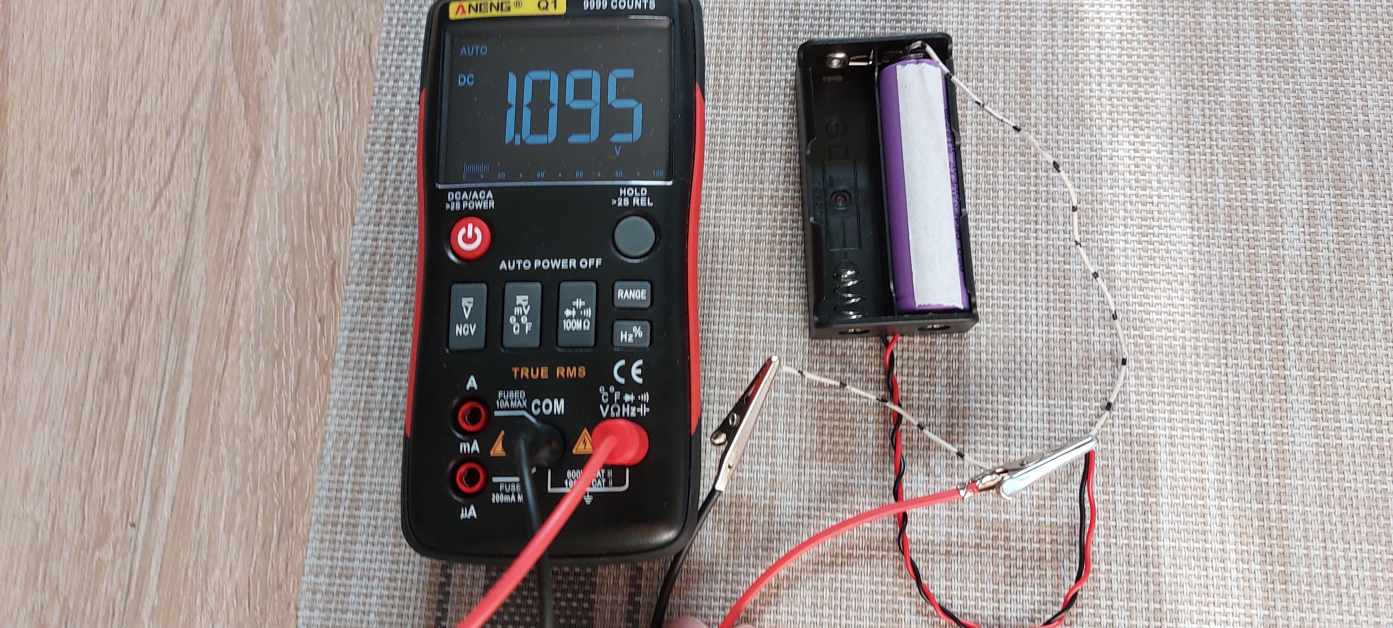
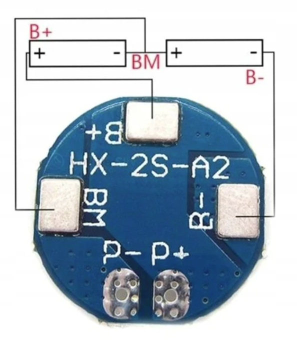
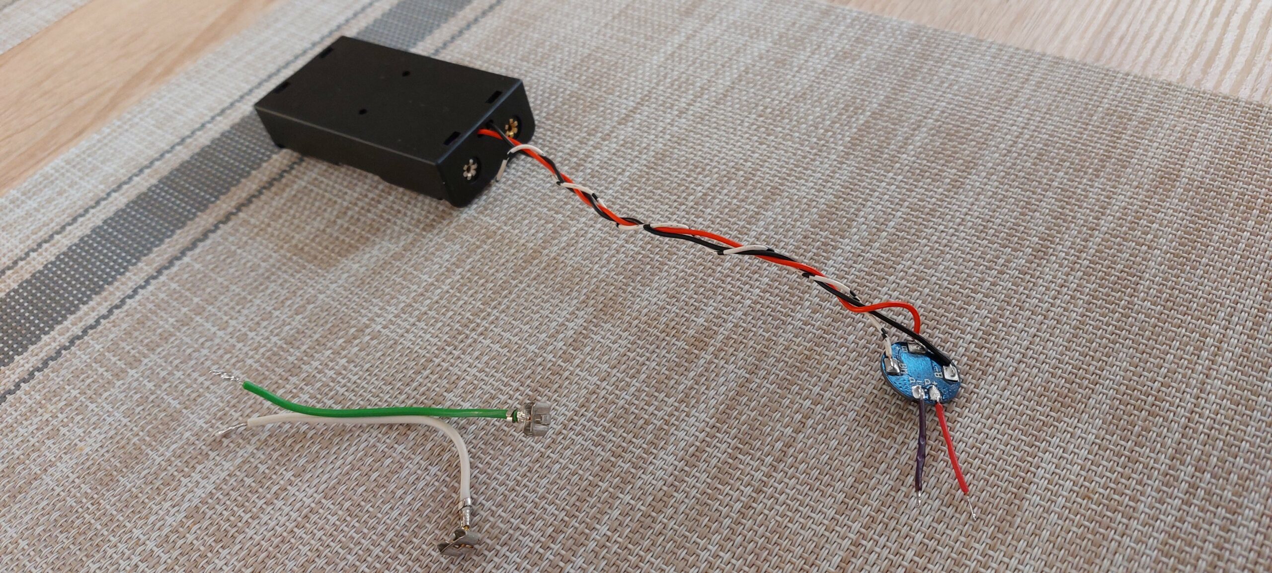
We will charge these cells from our power terminals from any power supply, so we need to have some overcharging protective circuit. We are gonna use this nice 2S 5A BMS module, but there is no status led’s on it so that’s why we have our Voltmeter so we can use it to check voltage amount. This module needs one additional wire between two cells, here is the schematic:
On the output of the module (P- and P+ terminals) we will have about 8V max when fully charged. Ideally we would like to have 12V but it’s enough to power up the amp and do some 5V logic digital circuits on the breadboard using some power regulator or step down/up converters.
This is the test circuit connected straight to the power terminals but I found out that this will limit using these terminals with higher voltages, because BMS will short out the terminals with voltage higher than 8V which is battery cell limit.
To prevent that we need to use switch to cut out our power from the battery when not used. Second switch cuts out power to the audio amp because it’s has max input of 12V. So now we can use external power supply with more than 12V if needed. But if you want to charge batteries turn the switch on and be careful to not input more than 8V.
Now when we have planned position of all elements, we have some space left inside enclosure that we can use somehow. We can use it for future ideas but for now I noticed there are some materials left so why not to make a handy drawer for some stuff?
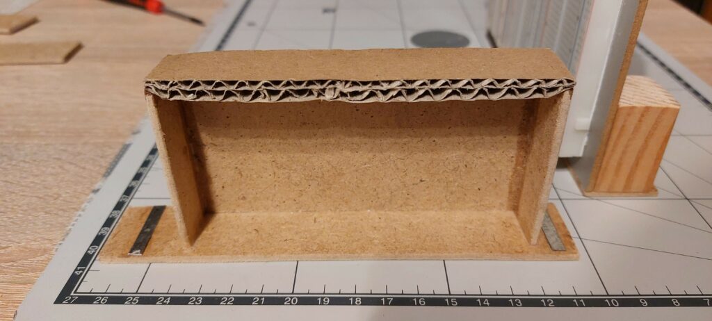
I didn’t have enough wood to make full drawer so I used some piece of cardboard, it will do 😀
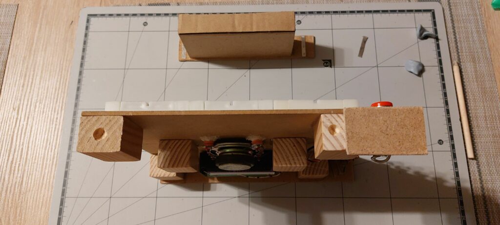
Our drawer will held on by small neodymium magnets, so we need to glue some metal strips to the drawer inside walls and drill smal holes for magnets in the support pieces and attach them with some strong wood/metal glue.
Now we need to put everything together, glue side panels to the supports, screw bottom pieces to the supports with some rubber feet’s so we can always open the enclosure.
Added some more glue in the corners of the back side panel as it is only attached by edges. But first you should solder all components to the terminals because there will bo not much space for soldering iron.
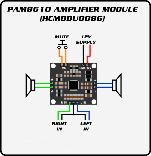
As our audio amp I used this nice PAM8610 module, without mute switch, attached with double sided 3M tape to the enclosure.
Right output channel is connected to the side panel terminals. Left output channel is connected also to the speaker push in terminals and built-in speaker itself, so you can use it with external audio source for example coming out from circuit on the breadboard. But you must switch amp off by disconnecting it’s power either from the battery or external power source.
Right and left amp input channels are connected to the breadboard terminals and 6.3mm audio jacks so you can amplify signal coming from either external audio source or breadboard.
Notice I added some pin headers to the BMS output to easy detach battery holder if I decide to add more cells in the future. More cells means using different BMS or charger module so it’s shouldn’t be permanently attached.
Now we can glue the front panel, also solder all wires to the switches and Voltmeter first.
Now we can secure all loose wires and attach them to whatever we can, so they will not rattle inside.
I attach switches with wood/metal glue to the side panel, attach bottom panels and that’s it! We can test the board 🙂
Oh yeah adding some informative labels would be nice 😀
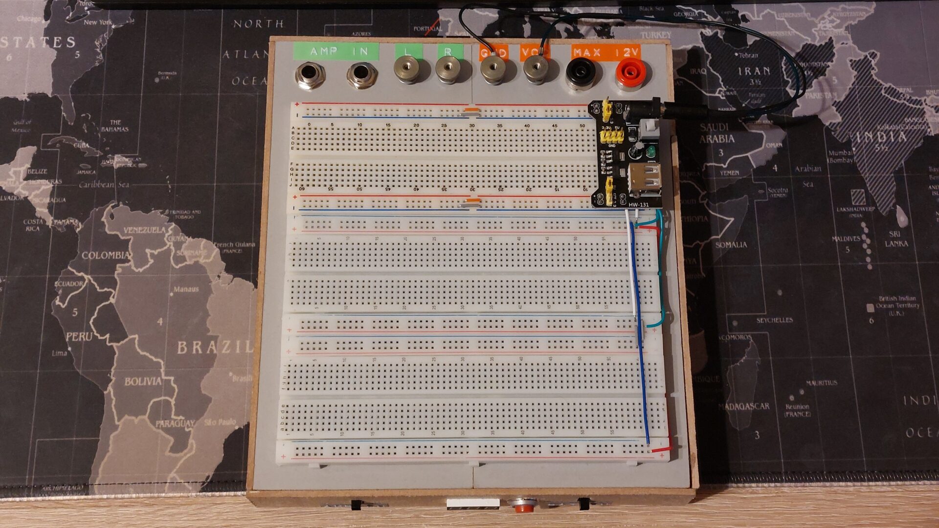
I made some wire with DC barrel plug to be able to connect battery to this power regulator for breadboards so I can use 5V or 3.3V digital logic. Nice thing!
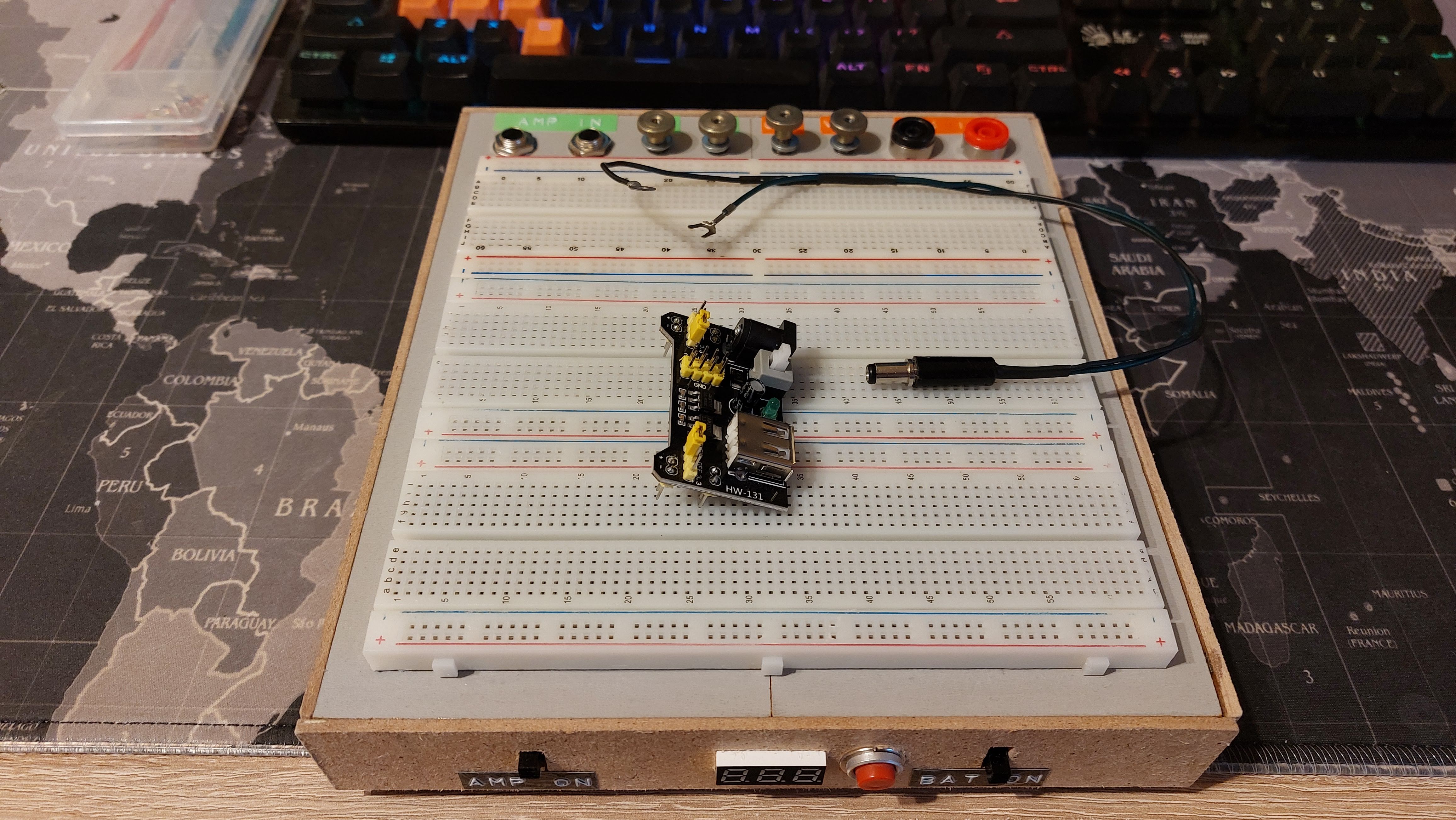
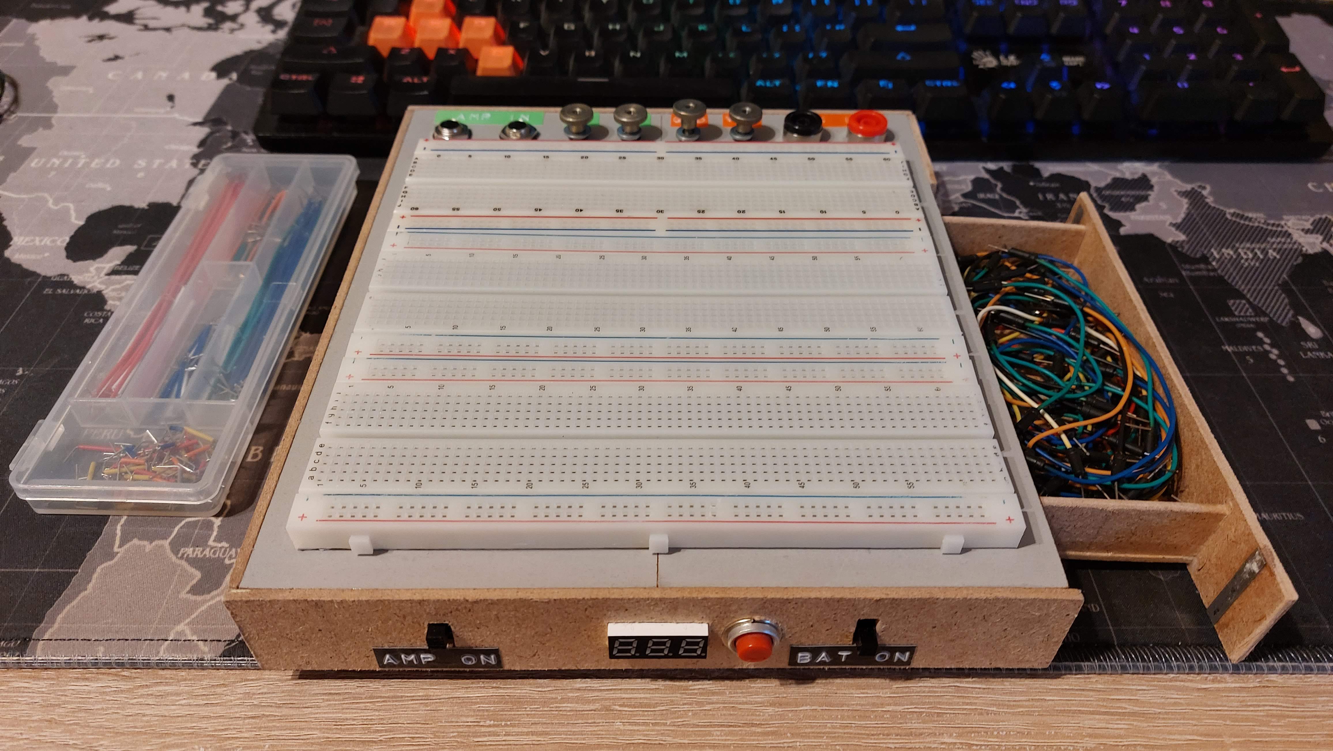
Finished test setup, ready to make some wonderful audio circuits 😀
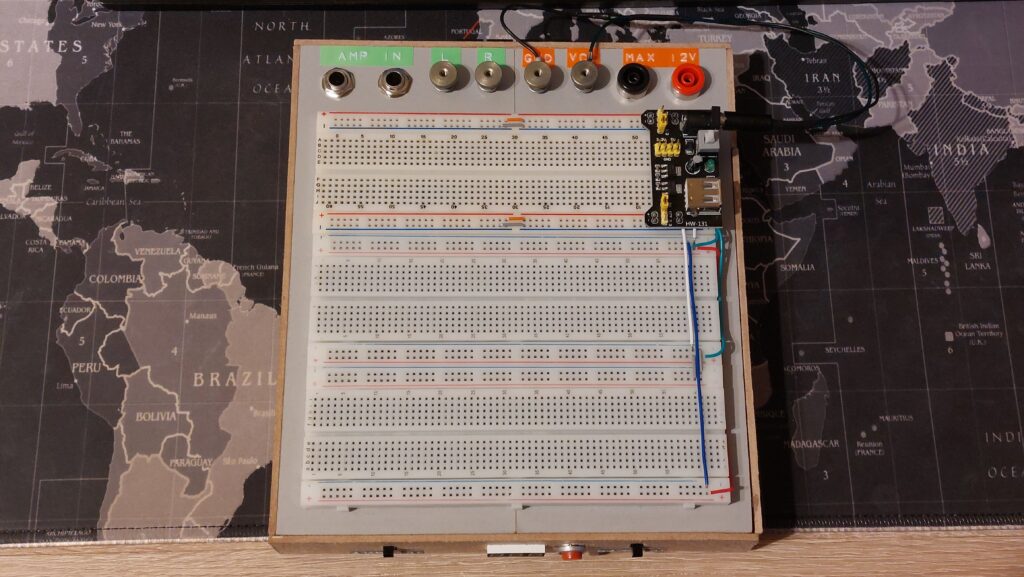
In case any one wonders, here are the finished board dimensions:
Length – 21.5 cm, Width – 19 cm, Height – 3 cm.
Parts used: